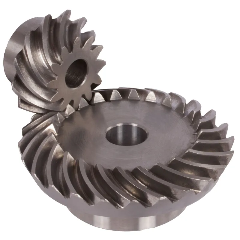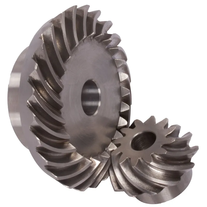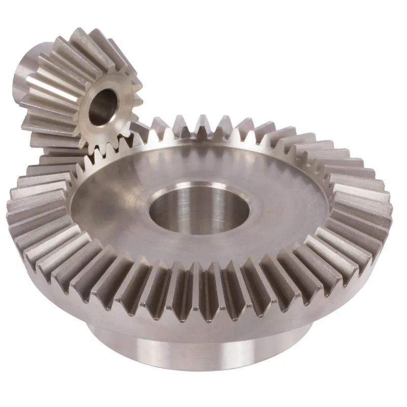
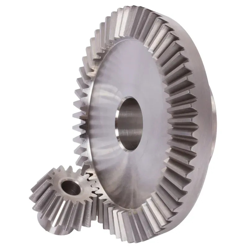
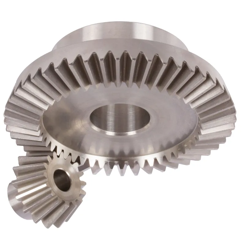
เฟืองเฉียงสแตนเลส อัตราทด 4:1 ระบบฟันตรง
ระบบเฟืองเฉียงสแตนเลสอัตราส่วน 4:1 แบบฟันตรง เป็นชุดเฟืองเชิงกลที่ออกแบบมาเพื่อการส่งกำลังอย่างมีประสิทธิภาพระหว่างเพลาสองอันที่ตัดกัน โดยทั่วไปจะทำมุมฉาก (90°) เฟืองเฉียงเหล่านี้ทำจากสแตนเลสที่ทนทาน ให้ความต้านทานต่อการกัดกร่อน การสึกหรอ และสภาพแวดล้อมที่มีอุณหภูมิสูงได้ดีเยี่ยม ทำให้เหมาะสำหรับการใช้งานในอุตสาหกรรมที่ต้องการความทนทานสูง
ระบบเฟืองเฉียงสแตนเลสอัตราส่วน 4:1 แบบฟันตรง เป็นชุดเฟืองเชิงกลที่ออกแบบมาเพื่อการส่งกำลังอย่างมีประสิทธิภาพระหว่างเพลาสองอันที่ตัดกัน โดยทั่วไปจะทำมุมฉาก (90°) เฟืองเฉียงเหล่านี้ทำจากสแตนเลสที่ทนทาน ให้ความต้านทานต่อการกัดกร่อน การสึกหรอ และสภาพแวดล้อมที่มีอุณหภูมิสูงได้ดีเยี่ยม ทำให้เหมาะสำหรับการใช้งานในอุตสาหกรรมที่ต้องการความทนทานสูง
คำว่าอัตราส่วน 4:1 หมายความว่าเฟืองตัวเล็ก (เฟืองขับ) หมุนครบ 4 รอบต่อการหมุน 1 รอบของเฟืองตัวใหญ่ ซึ่งช่วยลดความเร็วได้อย่างมากในขณะที่เพิ่มแรงบิด การออกแบบฟันเฟืองแบบตรงหมายถึงฟันเฟืองที่เรียงตัวเป็นเส้นตรงในแนวรัศมี ซึ่งผลิตและจัดเรียงได้ง่ายกว่าเฟืองดอกจอกแบบเกลียว แม้ว่าจะเกิดเสียงดังกว่าเล็กน้อยเนื่องจากการขบกันของฟันเฟืองอย่างกระทันหัน แต่ก็เหมาะสำหรับงานที่ใช้ความเร็วต่ำถึงปานกลางซึ่งต้องการความแม่นยำและความทนทาน
อัตราทดเฟืองเฉียงสแตนเลส 4:1
| 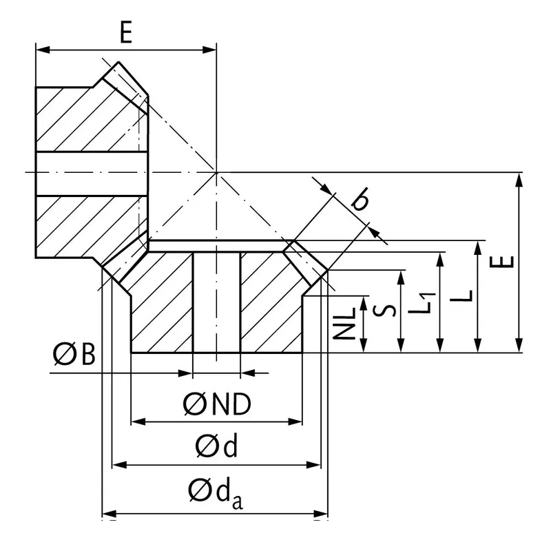 |
| โมดูล | ตัวเลข ของฟัน | งเอ | ง | เอ็นดี | เอ็นแอล | แอล1 | แอล | เอส | ข | บีเอช7 | อี | แรงบิด* | น้ำหนัก |
| มม. | มม. | มม. | มม. | มม. | มม. | มม. | มม. | มม. | มม. | เอ็นซีเอ็ม | จี | ||
| 1 | 15 | 17,8 | 15 | 13 | 7,7 | 17,3 | 17,3 | 8,4 | 9,3 | 5 | 38 | 0,14 | 15 |
| 1 | 60 | 60,3 | 60 | 30 | 10,0 | 15 | 17,1 | 15,1 | 9,3 | 8 | 22 | 0,56 | 160 |
| 1,5 | 15 | 26,7 | 22,5 | 18 | 14,45 | 28 | 28,9 | 15,5 | 13,9 | 8 | 60 | 0,48 | 42 |
| 1,5 | 60 | 90,4 | 90 | 50 | 12,0 | 25 | 27,6 | 24,6 | 13,9 | 15 | 35 | 1,92 | 745 |
| 2 | 15 | 34,0 | 30 | 20 | 13,5 | 29 | 29,9 | 15,5 | 15 | 10 | 75 | 1,34 | 80 |
| 2 | 60 | 120,9 | 120 | 60 | 20,0 | 35 | 40,1 | 37,0 | 15 | 25 | 50 | 5,36 | 1600 |
| 2,5 | 15 | 42,5 | 37,5 | 30 | 16,1 | 35 | 36,8 | 17,6 | 20 | 10 | 92 | 2,5 | 190 |
| 2,5 | 60 | 151,2 | 150 | 80 | 18,0 | 33 | 37,8 | 33,8 | 20 | 25 | 50 | 10,0 | 2600 |
| 3 | 15 | 51,0 | 45 | 30 | 13,15 | 38 | 39,7 | 15,7 | 25 | 10 | 105 | 4,4 | 270 |
| 3 | 60 | 181,5 | 180 | 80 | 18,0 | 35 | 40,6 | 35,5 | 25 | 30 | 55 | 17,6 | 3800 |
| 4 | 15 | 68,0 | 60 | 40 | 12,5 | 43 | 44,8 | 16,0 | 30 | 20 | 135 | 8,9 | 520 |
| 4 | 60 | 242,0 | 240 | 90 | 20,0 | 41 | 50,1 | 44,0 | 30 | 30 | 70 | 35,6 | 8300 |
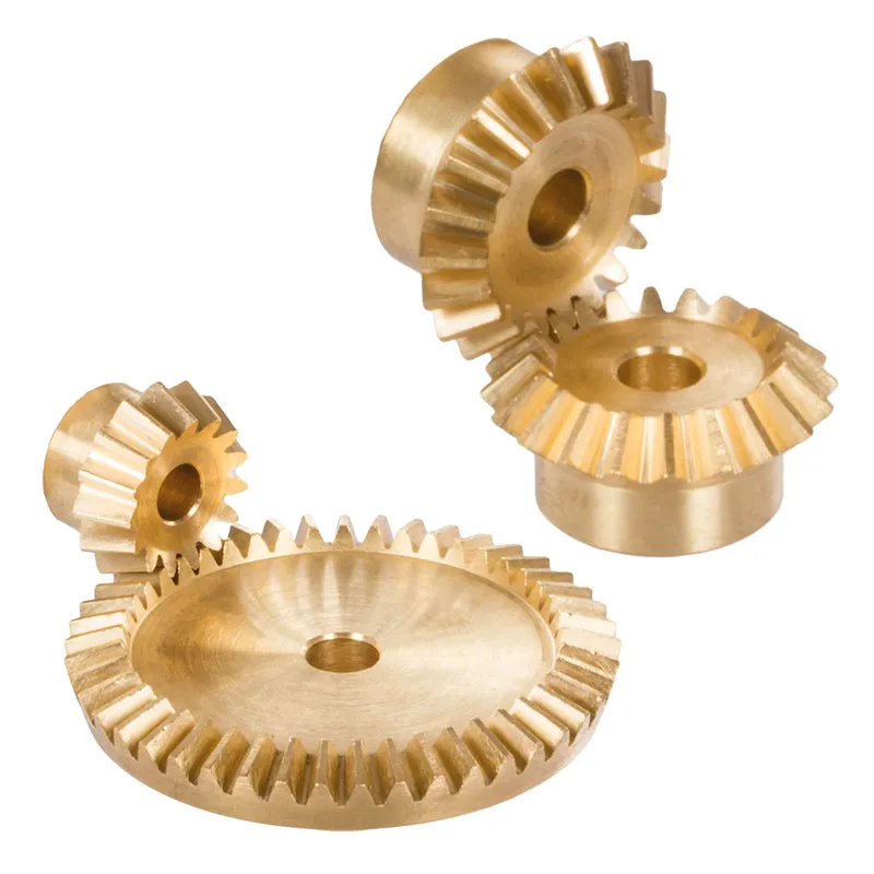
ข้อดีของเฟืองดอกจอกสแตนเลส
ความสามารถในการรับแรงบิดสูง
ข้อดีสำคัญประการหนึ่งของเฟืองดอกจอกสแตนเลสคือความสามารถในการรับแรงบิดสูง รูปทรงและการออกแบบของเฟืองดอกจอกช่วยให้การส่งกำลังและแรงบิดระหว่างเพลาที่ตัดกันเป็นไปอย่างมีประสิทธิภาพ
ดีไซน์กะทัดรัด
เฟืองดอกจอกเป็นทางเลือกที่กะทัดรัดสำหรับการส่งกำลังระหว่างเพลาที่ไม่ขนานกัน ด้วยการใช้รูปทรงกรวย เฟืองดอกจอกสามารถเปลี่ยนทิศทางการหมุนได้อย่างมีประสิทธิภาพภายในพื้นที่จำกัด
การทำงานราบรื่นและเงียบ
เมื่อได้รับการออกแบบและผลิตอย่างเหมาะสม เฟืองดอกจอกสามารถให้การทำงานที่ราบรื่นและเงียบ การพัฒนาด้านรูปทรงเรขาคณิตของฟันเฟือง เช่น การใช้เฟืองดอกจอกแบบเกลียวและเฟืองไฮปอยด์ ได้ปรับปรุงความราบรื่นและความสามารถในการลดเสียงรบกวนของเฟืองดอกจอกอย่างมาก โปรไฟล์ฟันโค้งของเฟืองดอกจอกแบบเกลียวช่วยให้การเข้าและออกจากกันเป็นไปอย่างค่อยเป็นค่อยไป ส่งผลให้การทำงานเงียบกว่าเมื่อเทียบกับเฟืองดอกจอกแบบตรง
ความยืดหยุ่นในการปรับมุมของก้านไม้กอล์ฟ
เฟืองดอกจอกมีความยืดหยุ่นในแง่ของมุมเพลาที่สามารถรองรับได้ แม้ว่ามุมเพลาที่พบได้บ่อยที่สุดสำหรับเฟืองดอกจอกคือ 90 องศา แต่ก็สามารถออกแบบให้ใช้งานร่วมกับมุมเพลาต่างๆ ได้
ข้อเสียของเฟืองดอกจอกสแตนเลส
ความซับซ้อนในการผลิตที่สูงขึ้น
ข้อเสียเปรียบหลักอย่างหนึ่งของเฟืองดอกจอกสแตนเลสคือ ความซับซ้อนในการผลิตที่สูงกว่าเมื่อเทียบกับเฟืองประเภทอื่น เช่น เฟืองตรง การผลิตเฟืองดอกจอกต้องใช้เครื่องจักรเฉพาะทางและกระบวนการผลิตที่แม่นยำเพื่อให้ได้รูปทรงฟันและผิวสำเร็จตามที่ต้องการ ความซับซ้อนนี้อาจส่งผลให้ต้นทุนการผลิตสูงขึ้นและระยะเวลารอคอยนานขึ้น
ความไวต่อการเบี่ยงเบน
เฟืองดอกจอกมีความไวต่อการเยื้องศูนย์มากกว่าเฟืองประเภทอื่น การเยื้องศูนย์อาจนำไปสู่การกระจายแรงที่ไม่สม่ำเสมอ ความเครียดที่เพิ่มขึ้นบนฟันเฟือง และความเสียหายก่อนกำหนด
ขีดจำกัดความเร็ว
เฟืองดอกจอกมีข้อจำกัดในด้านความเร็ว ที่ความเร็วสูง เฟืองดอกจอกมักจะเกิดเสียงและแรงสั่นสะเทือนมากเกินไปเนื่องจากการเลื่อนระหว่างฟันเฟือง ซึ่งอาจนำไปสู่ประสิทธิภาพที่ลดลงและการสึกหรอที่เพิ่มขึ้น ดังนั้น เฟืองดอกจอกจึงมักใช้ในงานที่ต้องการความเร็วปานกลางถึงต่ำ
ต้นทุนที่สูงขึ้น
ความซับซ้อนและความแม่นยำในการผลิตเฟืองดอกจอกมักส่งผลให้ต้นทุนสูงกว่าเฟืองประเภทอื่น ๆ ความจำเป็นต้องใช้เครื่องจักรเฉพาะทาง แรงงานฝีมือ และมาตรการควบคุมคุณภาพที่เข้มงวด ล้วนเป็นปัจจัยที่ทำให้ต้นทุนของเฟืองดอกจอกสูงขึ้น นอกจากนี้ การปรับแต่งและการออกแบบเฉพาะของเฟืองดอกจอกสำหรับงานเฉพาะด้านก็อาจทำให้ต้นทุนสูงขึ้นไปอีก
เฟืองดอกจอกใช้สำหรับอะไร
การส่งกำลังในรถยนต์
เฟืองดอกจอกมีการใช้งานอย่างแพร่หลายในอุตสาหกรรมยานยนต์ โดยเฉพาะอย่างยิ่งในระบบขับเคลื่อนเฟืองท้าย ในเฟืองท้าย เฟืองดอกจอกแบบตรงจะถูกใช้เพื่อแบ่งกำลังจากเพลาขับและส่งไปยังล้อ ในขณะที่อนุญาตให้ล้อหมุนด้วยความเร็วที่แตกต่างกัน ซึ่งช่วยให้การเข้าโค้งราบรื่นและควบคุมการยึดเกาะถนนได้ดีขึ้น เฟืองดอกจอกยังใช้ในงานยานยนต์อื่นๆ อีกหลายอย่าง เช่น ชุดเกียร์ถ่ายกำลังและระบบบังคับเลี้ยว
เครื่องจักรกลอุตสาหกรรม
เฟืองดอกจอกเป็นเฟืองที่ใช้กันทั่วไปในเครื่องจักรกลอุตสาหกรรมที่ต้องการส่งกำลังระหว่างเพลาที่ตัดกัน พบได้ในอุปกรณ์หลากหลายประเภท เช่น เกียร์ทดรอบ ชุดลดความเร็ว และระบบส่งกำลัง การใช้งานในอุตสาหกรรมที่ใช้เฟืองดอกจอก ได้แก่ เครื่องจักรเหมืองแร่ อุปกรณ์ก่อสร้าง เครื่องพิมพ์ และเครื่องจักรสิ่งทอ
การบินและอวกาศ
อุตสาหกรรมการบินและอวกาศพึ่งพาเฟืองดอกจอกสแตนเลสสำหรับการส่งกำลังในงานต่างๆ เฟืองดอกจอกใช้ในเครื่องยนต์อากาศยาน ระบบขับเคลื่อนใบพัด และกล่องเกียร์เสริมต่างๆ ได้รับการออกแบบให้รับภาระสูงและให้ประสิทธิภาพที่เชื่อถือได้ในสภาวะการทำงานที่ต้องการความแม่นยำสูง การออกแบบที่กะทัดรัดและความสามารถในการส่งกำลังระหว่างเพลาที่ไม่ขนานกัน ทำให้เฟืองดอกจอกเหมาะอย่างยิ่งสำหรับงานด้านการบินและอวกาศที่พื้นที่จำกัด
การใช้งานทางทะเล
เฟืองดอกจอกถูกนำมาใช้ในงานทางทะเลสำหรับการส่งกำลังในระบบขับเคลื่อน ระบบบังคับเลี้ยว และเครื่องจักรบนดาดฟ้าเรือ โดยใช้ในเกียร์บ็อกซ์ เครื่องขับดัน และเครื่องกว้าน ความสามารถของเฟืองดอกจอกในการรับแรงบิดสูงและทนทานต่อสภาพแวดล้อมทางทะเลที่รุนแรงทำให้เหมาะสำหรับงานเหล่านี้ เฟืองดอกจอกสำหรับงานทางทะเลมักผลิตจากวัสดุที่ทนต่อการกัดกร่อนเพื่อให้มั่นใจในความทนทานและความน่าเชื่อถือ
 |  |
| เฟืองดอกจอกสำหรับเฟืองท้ายรถยนต์ | เฟืองดอกจอกสำหรับเครื่องจักรอุตสาหกรรม |
 |  |
| เฟืองดอกจอกสำหรับหุ่นยนต์ | เฟืองดอกจอกสำหรับอุตสาหกรรมทางทะเล |
การวัดเฟืองเฉียงสแตนเลส
ขั้นตอนที่ 1: รวบรวมเครื่องมือและอุปกรณ์ที่จำเป็น
ในการวัดเฟืองดอกจอกอย่างแม่นยำ คุณจะต้องใช้เครื่องมือต่อไปนี้:
- เวอร์เนียร์คาลิเปอร์หรือไมโครมิเตอร์สำหรับวัดความหนา ความลึก และเส้นผ่านศูนย์กลางของฟันเฟือง
- ไม้โปรแทรกเตอร์แบบเอียงสำหรับวัดมุมเอียงและมุมโคนต้นไม้
- เวอร์เนียร์คาลิเปอร์วัดฟันเฟือง สำหรับวัดความหนาของฟันเฟืองที่ความลึกเฉพาะเจาะจง
- แผ่นฐานและเกจวัดความสูงสำหรับตรวจสอบการเบี่ยงเบนของเฟืองและระยะการติดตั้ง
ขั้นตอนที่ 2: วัดเส้นผ่านศูนย์กลางของเกลียว
วิธีการวัดเส้นผ่านศูนย์กลางของเกลียว:
- วางเฟืองดอกจอกบนแผ่นพื้นผิวโดยให้ด้านหลังคว่ำลง
- วางเกจวัดความสูงให้ตั้งฉากกับแผ่นพื้นผิว และจัดตำแหน่งปลายวัดให้ตรงกับเส้นพิทช์บนด้านข้างของฟันเฟือง
- ตั้งค่ามาตรวัดความสูงเป็นศูนย์ที่ตำแหน่งนี้
- หมุนเฟือง 180 องศา แล้ววัดความสูงที่เส้นพิทช์ที่สอดคล้องกันบนด้านตรงข้ามของฟันเฟือง
- ระยะห่างระหว่างเกลียวคำนวณได้จากการบวกค่าความสูงทั้งสองเข้าด้วยกัน
ทำซ้ำขั้นตอนนี้กับฟันเฟืองหลายๆ ซี่รอบๆ เฟือง เพื่อให้แน่ใจว่ามีความสม่ำเสมอและตรวจสอบปัญหาการเบี่ยงเบนที่อาจเกิดขึ้น
ขั้นตอนที่ 3: วัดความหนาของฟัน
วิธีการวัดความหนาของฟัน:
- ใช้เวอร์เนียร์คาลิเปอร์วัดฟันเฟือง โดยวางเวอร์เนียร์คาลิเปอร์ให้ตรงกับเส้นพิทช์
- วัดความหนาของฟันตรงแนวร่องฟัน โดยระมัดระวังอย่าให้รูปทรงของฟันเสียหาย
- ทำการวัดซ้ำในฟันเฟืองหลายๆ ซี่ โดยสังเกตความแตกต่างที่พบ
อีกทางเลือกหนึ่งคือ สามารถใช้เวอร์เนียร์คาลิเปอร์หรือไมโครมิเตอร์มาตรฐานในการวัดความหนาของเส้นเอ็นบริเวณโคนฟันได้
ขั้นตอนที่ 4: วัดแรงดันและมุมรากฟัน
วิธีการวัดมุมเหล่านี้:
- วางไม้โปรแทรกเตอร์แบบเอียงลงบนกรวยระยะห่างของเฟือง โดยจัดแนวขอบของไม้โปรแทรกเตอร์ให้ตรงกับด้านข้างของฟันเฟือง
- อ่านค่ามุมแรงกดโดยตรงจากมาตราส่วนของไม้โปรแทรกเตอร์ ณ จุดสัมผัสกับรูปทรงของฟัน
- ปรับตำแหน่งไม้โปรแทรกเตอร์ให้ตรงกับแนวรากฟันเพื่อวัดมุมรากฟัน
ตรวจสอบว่ามุมที่วัดได้ตรงกับพารามิเตอร์การออกแบบเฟืองที่ระบุไว้
ขั้นตอนที่ 5: ตรวจสอบความคลาดเคลื่อนของเฟือง
การเบี่ยงเบนของเฟือง หมายถึงความแปรผันของรูปทรงเรขาคณิตของเฟืองขณะหมุนรอบแกน วิธีตรวจสอบการเบี่ยงเบนของเฟือง:
- ติดตั้งเฟืองดอกจอกบนแกนหรือเพลาที่รองรับด้วยบล็อกรูปตัววีบนแผ่นฐาน
- วางเครื่องวัดความเที่ยงตรงแบบหน้าปัด โดยให้หัววัดสัมผัสกับด้านหลังของเฟืองใกล้กับเส้นผ่านศูนย์กลางภายนอก
- ค่อยๆ หมุนเฟือง โดยสังเกตค่าการอ่านตัวบ่งชี้รวม (TIR) บนหน้าปัด
- เปรียบเทียบค่า TIR ที่วัดได้กับค่าความคลาดเคลื่อนที่ระบุไว้สำหรับการเบี่ยงเบนของแกนหมุน
ทำซ้ำขั้นตอนนี้ที่ด้านหน้าของเฟืองและที่เส้นผ่านศูนย์กลางของเกลียว เพื่อประเมินความคลาดเคลื่อนของเฟืองอย่างครบถ้วน
ขั้นตอนที่ 6: ตรวจสอบระยะห่างในการติดตั้ง
ระยะการติดตั้งคือตำแหน่งตามแนวแกนของเฟืองดอกจอกเทียบกับเฟืองคู่ประกบ วิธีการตรวจสอบระยะการติดตั้ง:
- วางเฟืองดอกจอกบนแผ่นพื้นผิวโดยให้ด้านหน้าคว่ำลง
- ใช้เกจวัดความสูงวัดระยะห่างจากแผ่นฐานถึงด้านหลังของเฟือง ณ รัศมีระยะการติดตั้งที่กำหนด
- เปรียบเทียบค่าที่วัดได้กับระยะการติดตั้งที่ออกแบบไว้ของเฟือง
ข้อมูลเพิ่มเติม
| เรียบเรียงโดย | วายเจเอ็กซ์ |
|---|