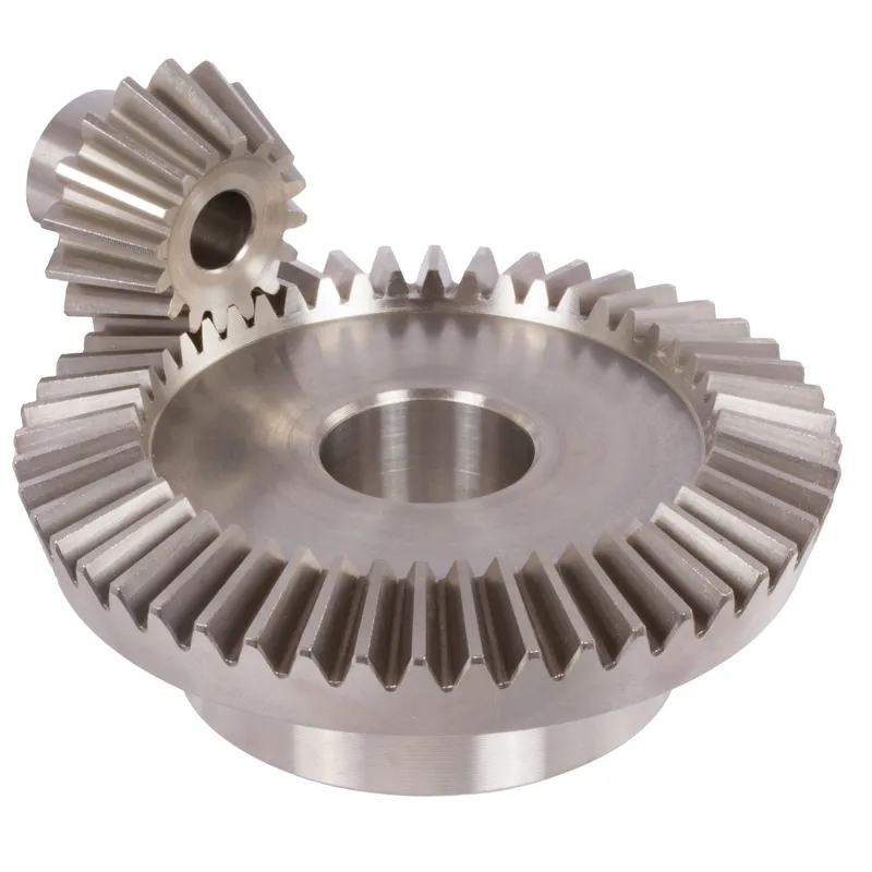
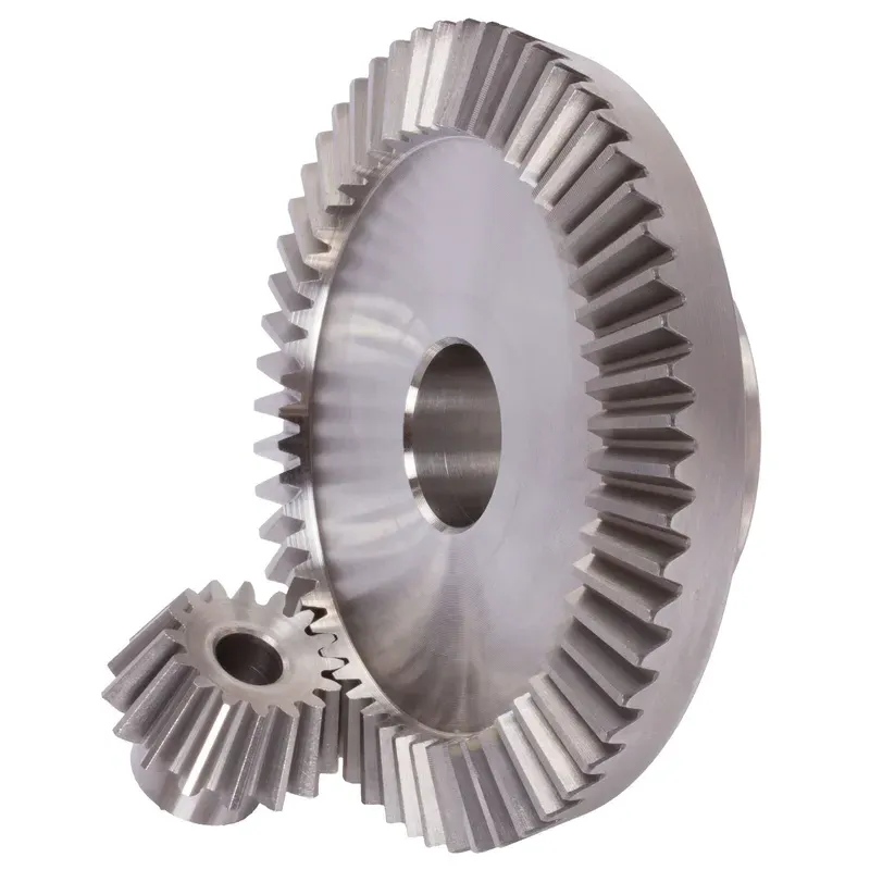
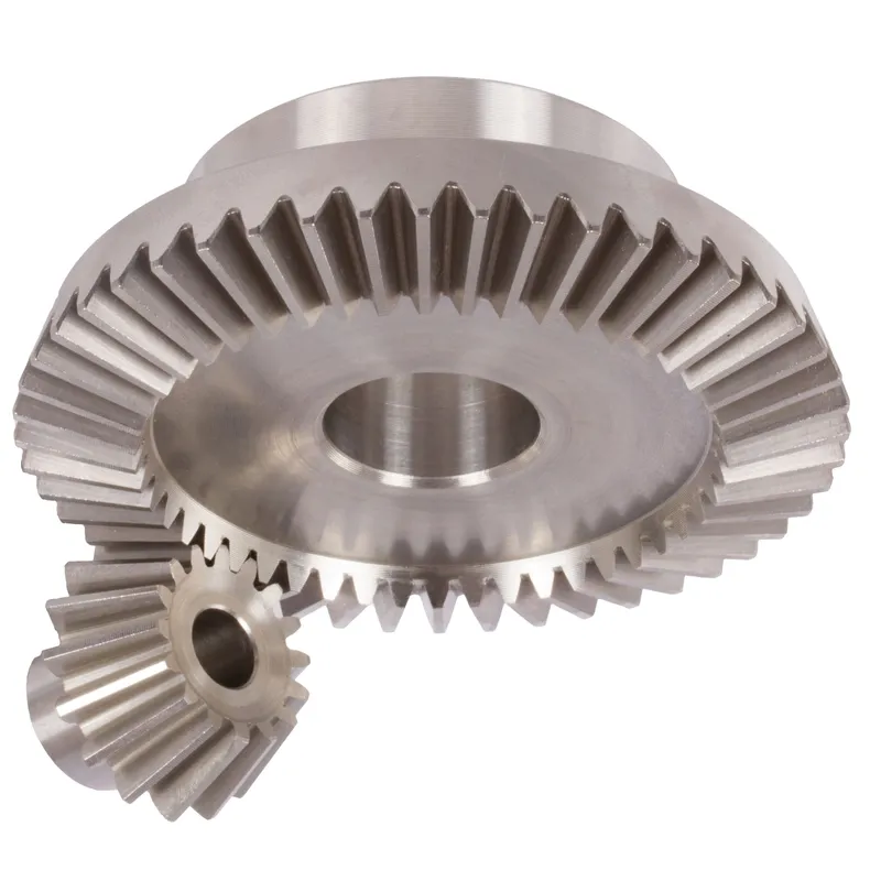
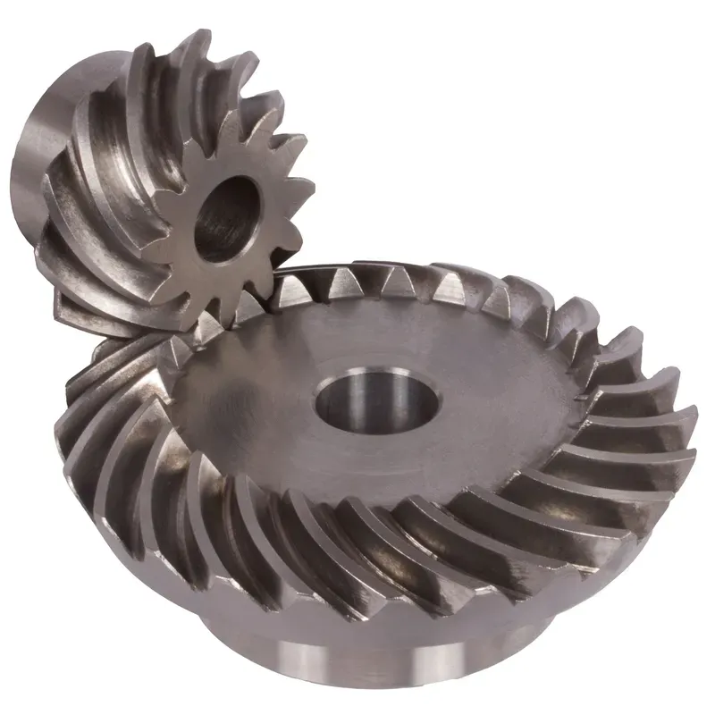
Sistema de engranajes cónicos de acero inoxidable con relación 4:1 y dientes rectos.
El sistema de engranajes cónicos de acero inoxidable con relación 4:1 y dientes rectos es un mecanismo diseñado para la transmisión eficiente de potencia entre dos ejes que se cruzan, generalmente en ángulo recto (90°). Estos engranajes cónicos están fabricados en acero inoxidable duradero, lo que les confiere una excelente resistencia a la corrosión, al desgaste y a las altas temperaturas, haciéndolos idóneos para aplicaciones industriales exigentes.
El sistema de engranajes cónicos de acero inoxidable con relación 4:1 y dientes rectos es un mecanismo diseñado para la transmisión eficiente de potencia entre dos ejes que se cruzan, generalmente en ángulo recto (90°). Estos engranajes cónicos están fabricados en acero inoxidable duradero, lo que les confiere una excelente resistencia a la corrosión, al desgaste y a las altas temperaturas, haciéndolos idóneos para aplicaciones industriales exigentes.
La relación 4:1 indica que el piñón (engranaje más pequeño) completa cuatro revoluciones por cada revolución del engranaje más grande. Esto permite una reducción significativa de la velocidad a la vez que amplifica el par motor. El diseño de dientes rectos se refiere a los dientes lineales dispuestos radialmente, que son más fáciles de fabricar y alinear en comparación con los engranajes cónicos espirales. Si bien son ligeramente más ruidosos debido al acoplamiento abrupto de los dientes, son ideales para aplicaciones de baja a moderada velocidad donde la precisión y la durabilidad son esenciales.
Engranaje cónico de acero inoxidable con relación 4:1
| 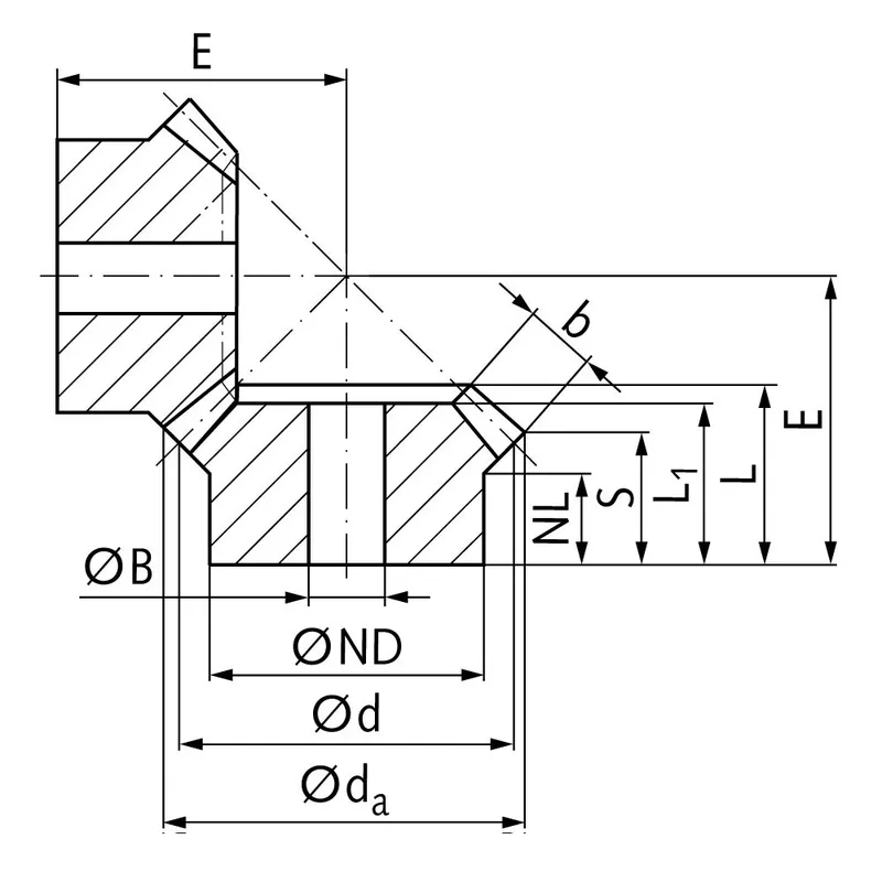 |
| Módulo | Número de dientes | da | d | DAKOTA DEL NORTE | Países Bajos | Yo1 | Yo | S | b | BH7 | mi | Esfuerzo de torsión* | Peso |
| mm | mm | mm | mm | mm | mm | mm | mm | mm | mm | Ncm | gramo | ||
| 1 | 15 | 17,8 | 15 | 13 | 7,7 | 17,3 | 17,3 | 8,4 | 9,3 | 5 | 38 | 0,14 | 15 |
| 1 | 60 | 60,3 | 60 | 30 | 10,0 | 15 | 17,1 | 15,1 | 9,3 | 8 | 22 | 0,56 | 160 |
| 1,5 | 15 | 26,7 | 22,5 | 18 | 14,45 | 28 | 28,9 | 15,5 | 13,9 | 8 | 60 | 0,48 | 42 |
| 1,5 | 60 | 90,4 | 90 | 50 | 12,0 | 25 | 27,6 | 24,6 | 13,9 | 15 | 35 | 1,92 | 745 |
| 2 | 15 | 34,0 | 30 | 20 | 13,5 | 29 | 29,9 | 15,5 | 15 | 10 | 75 | 1,34 | 80 |
| 2 | 60 | 120,9 | 120 | 60 | 20,0 | 35 | 40,1 | 37,0 | 15 | 25 | 50 | 5,36 | 1600 |
| 2,5 | 15 | 42,5 | 37,5 | 30 | 16,1 | 35 | 36,8 | 17,6 | 20 | 10 | 92 | 2,5 | 190 |
| 2,5 | 60 | 151,2 | 150 | 80 | 18,0 | 33 | 37,8 | 33,8 | 20 | 25 | 50 | 10,0 | 2600 |
| 3 | 15 | 51,0 | 45 | 30 | 13,15 | 38 | 39,7 | 15,7 | 25 | 10 | 105 | 4,4 | 270 |
| 3 | 60 | 181,5 | 180 | 80 | 18,0 | 35 | 40,6 | 35,5 | 25 | 30 | 55 | 17,6 | 3800 |
| 4 | 15 | 68,0 | 60 | 40 | 12,5 | 43 | 44,8 | 16,0 | 30 | 20 | 135 | 8,9 | 520 |
| 4 | 60 | 242,0 | 240 | 90 | 20,0 | 41 | 50,1 | 44,0 | 30 | 30 | 70 | 35,6 | 8300 |
Ventajas de los engranajes cónicos de acero inoxidable
Alta capacidad de par
Una de las principales ventajas de los engranajes cónicos de acero inoxidable es su capacidad para soportar altas cargas de torsión. La geometría y el diseño de los engranajes cónicos permiten una transmisión eficiente de potencia y torsión entre ejes que se cruzan.
Diseño compacto
Los engranajes cónicos ofrecen una solución compacta para la transmisión de potencia entre ejes no paralelos. Gracias a su geometría cónica, permiten cambiar eficazmente el sentido de giro en un espacio reducido.
Funcionamiento suave y silencioso
Cuando se diseñan y fabrican correctamente, los engranajes cónicos ofrecen un funcionamiento suave y silencioso. Los avances en la geometría de los dientes, como el uso de engranajes cónicos espirales e hipoides, han mejorado significativamente la suavidad y la reducción de ruido de los engranajes cónicos. El perfil curvo de los dientes de los engranajes cónicos espirales permite un acoplamiento y desacoplamiento gradual, lo que resulta en un funcionamiento más silencioso en comparación con los engranajes cónicos rectos.
Versatilidad en los ángulos del eje
Los engranajes cónicos ofrecen flexibilidad en cuanto a los ángulos de eje que pueden soportar. Si bien el ángulo de eje más común para los engranajes cónicos es de 90 grados, pueden diseñarse para funcionar con diversos ángulos de eje.
Desventajas de los engranajes cónicos de acero inoxidable
Mayor complejidad de fabricación
Una de las principales desventajas de los engranajes cónicos de acero inoxidable es su mayor complejidad de fabricación en comparación con otros tipos de engranajes, como los de dientes rectos. La producción de engranajes cónicos requiere maquinaria especializada y procesos de fabricación precisos para lograr la geometría de los dientes y el acabado superficial deseados. Esta complejidad puede resultar en mayores costos de fabricación y plazos de entrega más largos.
Sensibilidad a la desalineación
Los engranajes cónicos son más sensibles a la desalineación que otros tipos de engranajes. La desalineación puede provocar una distribución desigual de la carga, un aumento de la tensión en los dientes del engranaje y fallos prematuros.
Capacidad de velocidad limitada
Los engranajes cónicos presentan limitaciones en cuanto a su velocidad máxima. A altas velocidades, tienden a generar ruido y vibraciones excesivas debido al deslizamiento entre sus dientes, lo que puede reducir su eficiencia y aumentar el desgaste. Por consiguiente, se suelen utilizar en aplicaciones con requisitos de velocidad moderados o bajos.
Costo más elevado
La complejidad y precisión de fabricación que requieren los engranajes cónicos suelen traducirse en costes más elevados en comparación con otros tipos de engranajes más sencillos. La necesidad de maquinaria especializada, mano de obra cualificada y estrictos controles de calidad contribuye al aumento del coste de los engranajes cónicos. Además, la personalización y los requisitos de diseño específicos para aplicaciones particulares pueden incrementar aún más su precio.
¿Para qué se utilizan los engranajes cónicos?
Transmisión de potencia en automóviles
Los engranajes cónicos se utilizan ampliamente en la industria automotriz, especialmente en los diferenciales. En un diferencial, los engranajes cónicos rectos se emplean para distribuir la potencia del eje de transmisión y transmitirla a las ruedas, permitiendo que giren a diferentes velocidades. Esto facilita un paso por curva suave y un mejor control de la tracción. Los engranajes cónicos también se utilizan en otras aplicaciones automotrices, como cajas de transferencia y sistemas de dirección.
Maquinaria industrial
Los engranajes cónicos se utilizan comúnmente en maquinaria industrial donde se requiere transmitir potencia entre ejes que se cruzan. Se encuentran en una amplia gama de equipos, incluyendo cajas de engranajes, reductores de velocidad y sistemas de transmisión de potencia. Entre las aplicaciones industriales que utilizan engranajes cónicos se incluyen la maquinaria minera, la maquinaria de construcción, las imprentas y la maquinaria textil.
Aeroespacial y aviación
Las industrias aeroespacial y de aviación dependen de los engranajes cónicos de acero inoxidable para la transmisión de potencia en diversas aplicaciones. Estos engranajes se utilizan en motores de aeronaves, sistemas de transmisión de rotores y cajas de engranajes auxiliares. Están diseñados para soportar cargas elevadas y ofrecer un rendimiento fiable en condiciones de funcionamiento exigentes. Su diseño compacto y su capacidad para transmitir potencia entre ejes no paralelos hacen que los engranajes cónicos sean idóneos para aplicaciones aeroespaciales donde el espacio es limitado.
Aplicaciones marinas
Los engranajes cónicos se emplean en aplicaciones marinas para la transmisión de potencia en sistemas de propulsión, sistemas de dirección y maquinaria de cubierta. Se utilizan en cajas de engranajes, propulsores y cabrestantes marinos. Su capacidad para soportar altas cargas de torsión y resistir entornos marinos adversos los hace idóneos para estas aplicaciones. Los engranajes cónicos marinos suelen fabricarse con materiales resistentes a la corrosión para garantizar su durabilidad y fiabilidad.
 |  |
| Engranaje cónico para diferenciales automotrices | Engranaje cónico para maquinaria industrial |
 |  |
| Engranaje cónico para robótica | Engranajes cónicos para la industria marina |
Medición de engranajes cónicos de acero inoxidable
Paso 1: Reúna las herramientas y el equipo necesarios.
Para medir con precisión los engranajes cónicos, necesitará las siguientes herramientas:
- Calibrador Vernier o micrómetro para medir el espesor, la profundidad y el diámetro primitivo de los dientes.
- Transportador de bisel para medir ángulos de inclinación y raíz.
- Calibrador vernier para dientes de engranaje para medir el espesor de los dientes a una profundidad específica.
- Placa de superficie y medidor de altura para comprobar la excentricidad del engranaje y la distancia de montaje.
Paso 2: Medir el diámetro del paso
Para medir el diámetro del paso:
- Coloque el engranaje cónico sobre una placa de superficie con la cara posterior hacia abajo.
- Coloque el medidor de altura perpendicular a la placa de superficie y alinee su punta de medición con la línea de paso en el flanco de un diente de engranaje.
- Ponga a cero el indicador de altura en esta posición.
- Gire el engranaje 180 grados y mida la altura en la línea de paso correspondiente en el flanco opuesto del diente.
- El diámetro del paso se calcula sumando las dos medidas de altura.
Repita este proceso en varios dientes del engranaje para garantizar la uniformidad y comprobar si existen posibles problemas de excentricidad.
Paso 3: Medir el grosor del diente
Para medir el grosor del diente:
- Utilice un calibrador vernier de dientes de engranaje posicionado en la línea de paso.
- Mida el grosor de un diente en la línea de paso, teniendo cuidado de no dañar el perfil del diente.
- Repita esta medición en varios dientes del engranaje, anotando cualquier variación.
Como alternativa, se puede utilizar un calibrador vernier o un micrómetro estándar para medir el grosor de la cuerda en la base del diente.
Paso 4: Medir la presión y los ángulos de la raíz.
Para medir estos ángulos:
- Coloque el transportador de ángulos sobre el cono primitivo del engranaje, alineando su borde con el flanco de un diente.
- Lea el ángulo de presión directamente en la escala del transportador en el punto de tangencia con el perfil del diente.
- Reposicione el transportador para alinearlo con la línea de la raíz del diente y así medir el ángulo de la raíz.
Verifique que los ángulos medidos coincidan con los parámetros de diseño del engranaje especificados.
Paso 5: Inspeccionar la excentricidad del engranaje
La excentricidad de un engranaje se refiere a la variación en su geometría a medida que gira sobre su eje. Para comprobar la excentricidad:
- Monte el engranaje cónico sobre un mandril o eje sostenido por bloques en V sobre una placa de superficie.
- Coloque un comparador de cuadrante con su sonda en contacto con la cara posterior del engranaje, cerca del diámetro exterior.
- Gire lentamente el engranaje, observando la lectura total del indicador (TIR) en el dial.
- Compare el TIR medido con la tolerancia especificada para la desviación.
Repita este proceso en la cara frontal del engranaje y en el diámetro primitivo para evaluar completamente la excentricidad del engranaje.
Paso 6: Verificar la distancia de montaje
La distancia de montaje es la posición axial del engranaje cónico con respecto a su engranaje correspondiente. Para verificar la distancia de montaje:
- Coloque el engranaje cónico sobre una placa de superficie con su cara frontal hacia abajo.
- Utilice un medidor de altura para medir la distancia desde la placa de superficie hasta la cara posterior del engranaje en el radio de distancia de montaje especificado.
- Compare esta medida con la distancia de montaje prevista del engranaje.
Información adicional
| Editado por | Yjx |
|---|
Productos relacionados
-
Engranajes cónicos de acero inoxidable con relación 1:1 – 4:1 y sistema de dientes rectos
-
Sistema de engranajes cónicos de acero inoxidable con relación 2:1 y dientes rectos.
-
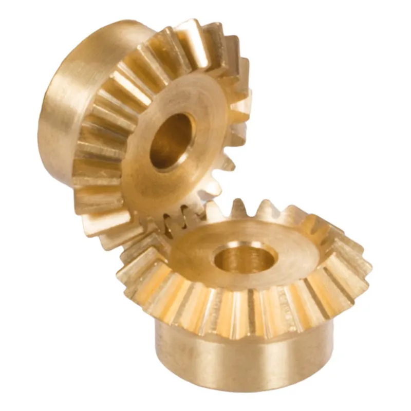
Engranajes cónicos de latón con relación 1:1 y sistema de dientes rectos
-
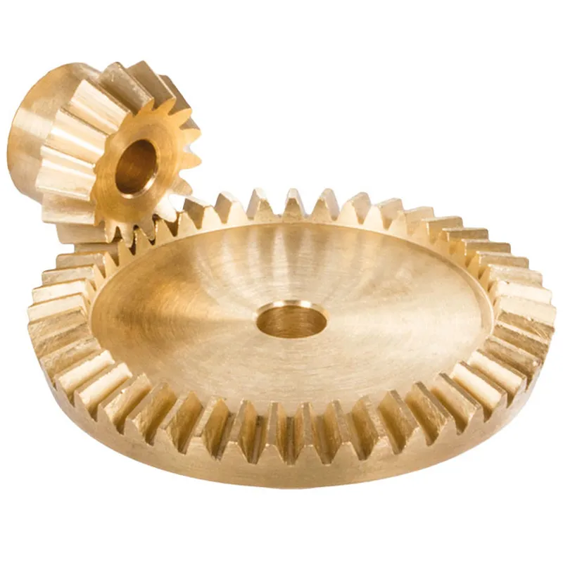
Engranajes cónicos de latón con relación 1,5:1 y sistema de dientes rectos
-
Engranajes cónicos espirales de acero con relación 1,5:1 y sistema de dientes espirales


