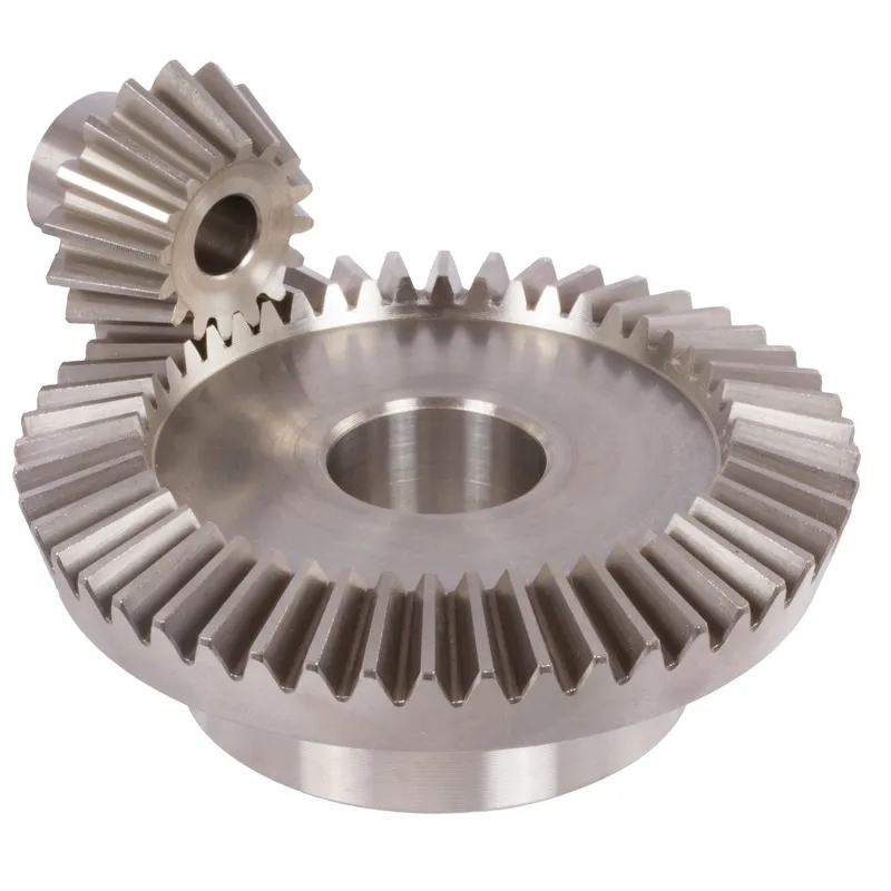
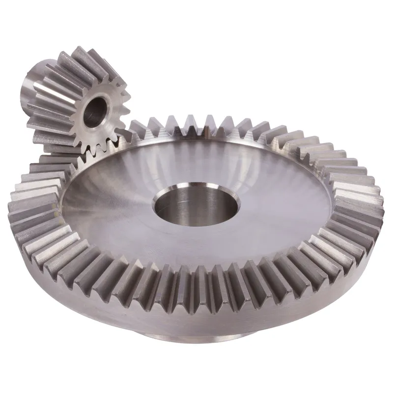
Engrenagens cônicas de aço inoxidável com relação de 4:1 e sistema de dentes retos.
O sistema de engrenagens cônicas de aço inoxidável com relação de 4:1 e dentes retos é um conjunto mecânico projetado para a transmissão eficiente de potência entre dois eixos que se cruzam, tipicamente em um ângulo reto (90°). Essas engrenagens cônicas são fabricadas em aço inoxidável durável, oferecendo excelente resistência à corrosão, ao desgaste e a ambientes de alta temperatura, tornando-as adequadas para aplicações industriais exigentes.
O sistema de engrenagens cônicas de aço inoxidável com relação de 4:1 e dentes retos é um conjunto mecânico projetado para a transmissão eficiente de potência entre dois eixos que se cruzam, tipicamente em um ângulo reto (90°). Essas engrenagens cônicas são fabricadas em aço inoxidável durável, oferecendo excelente resistência à corrosão, ao desgaste e a ambientes de alta temperatura, tornando-as adequadas para aplicações industriais exigentes.
A relação 4:1 indica que a engrenagem menor (pinhão) completa quatro rotações para cada rotação da engrenagem maior. Isso permite uma redução significativa na velocidade, ao mesmo tempo que amplifica o torque. O design de dentes retos refere-se aos dentes da engrenagem dispostos radialmente, que são mais simples de fabricar e alinhar em comparação com as engrenagens cônicas helicoidais. Embora sejam ligeiramente mais ruidosas devido ao engate abrupto dos dentes, são ideais para aplicações de baixa a moderada velocidade, onde a precisão e a durabilidade são essenciais.
Engrenagem cônica de aço inoxidável com relação de 4:1
| 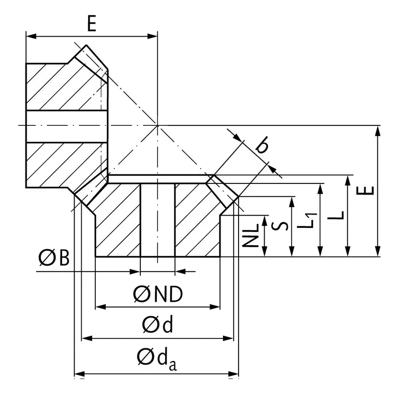 |
| Módulo | Número de dentes | dum | d | ND | Holanda | eu1 | eu | S | b | BH7 | E | Torque* | Peso |
| milímetros | milímetros | milímetros | milímetros | milímetros | milímetros | milímetros | milímetros | milímetros | milímetros | Ncm | g | ||
| 1 | 15 | 17,8 | 15 | 13 | 7,7 | 17,3 | 17,3 | 8,4 | 9,3 | 5 | 38 | 0,14 | 15 |
| 1 | 60 | 60,3 | 60 | 30 | 10,0 | 15 | 17,1 | 15,1 | 9,3 | 8 | 22 | 0,56 | 160 |
| 1,5 | 15 | 26,7 | 22,5 | 18 | 14,45 | 28 | 28,9 | 15,5 | 13,9 | 8 | 60 | 0,48 | 42 |
| 1,5 | 60 | 90,4 | 90 | 50 | 12,0 | 25 | 27,6 | 24,6 | 13,9 | 15 | 35 | 1,92 | 745 |
| 2 | 15 | 34,0 | 30 | 20 | 13,5 | 29 | 29,9 | 15,5 | 15 | 10 | 75 | 1,34 | 80 |
| 2 | 60 | 120,9 | 120 | 60 | 20,0 | 35 | 40,1 | 37,0 | 15 | 25 | 50 | 5,36 | 1600 |
| 2,5 | 15 | 42,5 | 37,5 | 30 | 16,1 | 35 | 36,8 | 17,6 | 20 | 10 | 92 | 2,5 | 190 |
| 2,5 | 60 | 151,2 | 150 | 80 | 18,0 | 33 | 37,8 | 33,8 | 20 | 25 | 50 | 10,0 | 2600 |
| 3 | 15 | 51,0 | 45 | 30 | 13,15 | 38 | 39,7 | 15,7 | 25 | 10 | 105 | 4,4 | 270 |
| 3 | 60 | 181,5 | 180 | 80 | 18,0 | 35 | 40,6 | 35,5 | 25 | 30 | 55 | 17,6 | 3800 |
| 4 | 15 | 68,0 | 60 | 40 | 12,5 | 43 | 44,8 | 16,0 | 30 | 20 | 135 | 8,9 | 520 |
| 4 | 60 | 242,0 | 240 | 90 | 20,0 | 41 | 50,1 | 44,0 | 30 | 30 | 70 | 35,6 | 8300 |
Vantagens das engrenagens cônicas de aço inoxidável
Alta capacidade de torque
Uma das principais vantagens das engrenagens cônicas de aço inoxidável é a sua capacidade de suportar cargas de torque elevadas. A geometria e o design das engrenagens cônicas permitem a transmissão eficiente de potência e torque entre eixos que se cruzam.
Design compacto
As engrenagens cônicas oferecem uma solução compacta para a transmissão de potência entre eixos não paralelos. Ao utilizar uma geometria cônica, as engrenagens cônicas podem alterar o sentido de rotação de forma eficaz em um espaço limitado.
Operação suave e silenciosa
Quando projetadas e fabricadas corretamente, as engrenagens cônicas podem proporcionar uma operação suave e silenciosa. Os avanços na geometria dos dentes das engrenagens, como o uso de engrenagens cônicas helicoidais e hipoides, melhoraram significativamente a suavidade e a capacidade de redução de ruído das engrenagens cônicas. O perfil curvo dos dentes das engrenagens cônicas helicoidais permite o engate e o desengate graduais, resultando em uma operação mais silenciosa em comparação com as engrenagens cônicas retas.
Versatilidade nos ângulos do eixo
As engrenagens cônicas oferecem flexibilidade em termos dos ângulos de eixo que podem acomodar. Embora o ângulo de eixo mais comum para engrenagens cônicas seja de 90 graus, elas podem ser projetadas para funcionar com diversos outros ângulos de eixo.
Desvantagens das engrenagens cônicas de aço inoxidável
Maior complexidade de fabricação
Uma das principais desvantagens das engrenagens cônicas de aço inoxidável é a sua maior complexidade de fabricação em comparação com outros tipos de engrenagens, como as engrenagens cilíndricas de dentes retos. A produção de engrenagens cônicas exige máquinas especializadas e processos de fabricação precisos para atingir a geometria dos dentes e o acabamento superficial desejados. Essa complexidade pode resultar em custos de fabricação mais elevados e prazos de entrega mais longos.
Sensibilidade ao desalinhamento
As engrenagens cônicas são mais sensíveis ao desalinhamento em comparação com outros tipos de engrenagens. O desalinhamento pode levar à distribuição desigual da carga, aumento da tensão nos dentes da engrenagem e falha prematura.
Capacidade de velocidade limitada
As engrenagens cônicas têm limitações em termos de capacidade de velocidade. Em altas velocidades, elas tendem a gerar ruído e vibração excessivos devido ao deslizamento entre os dentes. Isso pode levar à redução da eficiência e ao aumento do desgaste. Consequentemente, as engrenagens cônicas são normalmente utilizadas em aplicações com requisitos de velocidade moderados a baixos.
Custo mais elevado
A complexidade e a precisão de fabricação exigidas para engrenagens cônicas geralmente se traduzem em custos mais elevados em comparação com tipos de engrenagens mais simples. A necessidade de maquinário especializado, mão de obra qualificada e medidas rigorosas de controle de qualidade contribuem para o aumento do custo das engrenagens cônicas. Além disso, a personalização e os requisitos específicos de projeto das engrenagens cônicas para aplicações particulares podem aumentar ainda mais seu custo.
Para que servem as engrenagens cônicas?
Transmissão de potência em automóveis
As engrenagens cônicas são amplamente utilizadas na indústria automotiva, principalmente em diferenciais. Em um diferencial, as engrenagens cônicas retas são usadas para dividir a potência do eixo de transmissão e transmiti-la às rodas, permitindo que elas girem em velocidades diferentes. Isso possibilita curvas suaves e melhor controle de tração. As engrenagens cônicas também são usadas em diversas outras aplicações automotivas, como caixas de transferência e sistemas de direção.
Máquinas Industriais
Engrenagens cônicas são comumente usadas em máquinas industriais onde a potência precisa ser transmitida entre eixos que se cruzam. Elas são encontradas em uma ampla gama de equipamentos, incluindo caixas de engrenagens, redutores de velocidade e sistemas de transmissão de potência. Aplicações industriais que utilizam engrenagens cônicas incluem máquinas de mineração, equipamentos de construção, impressoras e máquinas têxteis.
Aeroespacial e Aviação
As indústrias aeroespacial e de aviação dependem de engrenagens cônicas de aço inoxidável para transmissão de potência em diversas aplicações. As engrenagens cônicas são utilizadas em motores de aeronaves, sistemas de acionamento de rotores e caixas de engrenagens auxiliares. Elas são projetadas para suportar altas cargas e proporcionar desempenho confiável em condições operacionais exigentes. O design compacto e a capacidade de transmitir potência entre eixos não paralelos tornam as engrenagens cônicas ideais para aplicações aeroespaciais onde o espaço é limitado.
Aplicações marítimas
As engrenagens cônicas são empregadas em aplicações marítimas para transmissão de potência em sistemas de propulsão, sistemas de direção e máquinas de convés. Elas são utilizadas em caixas de engrenagens, propulsores e guinchos marítimos. A capacidade das engrenagens cônicas de suportar altas cargas de torque e resistir a ambientes marítimos severos as torna adequadas para essas aplicações. As engrenagens cônicas marítimas são frequentemente fabricadas com materiais resistentes à corrosão para garantir durabilidade e confiabilidade.
 |  |
| Engrenagem cônica para diferenciais automotivos | Engrenagem cônica para máquinas industriais |
 |  |
| Engrenagem cônica para robótica | Engrenagens cônicas para a indústria marítima |
Medição de engrenagem cônica de aço inoxidável
Passo 1: Reúna as ferramentas e equipamentos necessários
Para medir engrenagens cônicas com precisão, você precisará das seguintes ferramentas:
- Paquímetro ou micrômetro para medir a espessura, a profundidade e o diâmetro primitivo dos dentes.
- Transferidor de bisel para medir ângulos de inclinação e de raiz.
- Paquímetro vernier para medir a espessura dos dentes de engrenagem em uma profundidade específica.
- Placa de superfície e medidor de altura para verificar a excentricidade da engrenagem e a distância de montagem.
Passo 2: Medir o diâmetro primitivo
Para medir o diâmetro primitivo:
- Coloque a engrenagem cônica sobre uma placa de superfície com a face traseira voltada para baixo.
- Posicione o medidor de altura perpendicularmente à placa de superfície e alinhe sua ponta de medição com a linha de passo na lateral de um dente da engrenagem.
- Zere o medidor de altura nesta posição.
- Gire a engrenagem 180 graus e meça a altura na linha primitiva correspondente no flanco oposto do dente.
- O diâmetro primitivo é calculado somando as duas medidas de altura.
Repita esse processo em vários dentes da engrenagem para garantir a consistência e verificar possíveis problemas de excentricidade.
Passo 3: Meça a espessura do dente
Para medir a espessura do dente:
- Utilize um paquímetro vernier para dentes de engrenagem posicionado na linha de passo.
- Meça a espessura de um dente na linha de passo, tomando cuidado para não danificar o perfil do dente.
- Repita essa medição em vários dentes da engrenagem, observando quaisquer variações.
Alternativamente, um paquímetro ou micrômetro padrão pode ser usado para medir a espessura da corda na base do dente.
Etapa 4: Medir a pressão e os ângulos da raiz
Para medir esses ângulos:
- Coloque o transferidor de ângulos no cone primitivo da engrenagem, alinhando sua borda com o flanco do dente.
- Leia o ângulo de pressão diretamente na escala do transferidor no ponto de tangência com o perfil do dente.
- Reposicione o transferidor para alinhá-lo com a linha da raiz do dente para medir o ângulo da raiz.
Verifique se os ângulos medidos correspondem aos parâmetros de projeto da engrenagem especificados.
Etapa 5: Inspecione o desalinhamento da engrenagem
A excentricidade da engrenagem refere-se à variação na geometria da engrenagem conforme ela gira em torno de seu eixo. Para verificar a excentricidade:
- Monte a engrenagem cônica em um mandril ou eixo apoiado por blocos em V em uma placa de superfície.
- Posicione um relógio comparador com sua ponta de prova em contato com a face traseira da engrenagem, próximo ao diâmetro externo.
- Gire a engrenagem lentamente, observando a leitura total do indicador (TIR) no mostrador.
- Compare o TIR medido com a tolerância especificada para excentricidade.
Repita esse processo na face frontal da engrenagem e no diâmetro primitivo para avaliar completamente a excentricidade da engrenagem.
Etapa 6: Verificar a distância de montagem
A distância de montagem é a posição axial da engrenagem cônica em relação à sua engrenagem de acoplamento. Para verificar a distância de montagem:
- Coloque a engrenagem cônica sobre uma placa de superfície com a face frontal voltada para baixo.
- Utilize um medidor de altura para medir a distância da placa de superfície até a face traseira da engrenagem, na distância de montagem especificada em raio.
- Compare essa medida com a distância de montagem projetada da engrenagem.
Informação adicional
| Editado por | Yjx |
|---|
Produtos relacionados
-
Engrenagens cônicas retas de aço com relação de 1:1 – 4:1, sistema de dentes retos
-
Engrenagens cônicas de aço inoxidável com relação 2:1 e sistema de dentes retos
-
Engrenagens cônicas de aço com relação de 1:1 e sistema de dentes retos
-
Engrenagens cônicas de aço inoxidável com relação de 1:1 a 4:1 e sistema de dentes retos.
-
Engrenagens cônicas espirais de aço com relação de 1,214:1 e sistema de dentes espirais.


