锥齿轮尺寸测量不准确会导致机械应用中性能下降、过早失效以及代价高昂的返工。尺寸不精确和与齿轮标准偏差会导致运行噪音增大、动力传输效率降低以及对准问题,这些问题甚至可能导致生产线停工。
锥齿轮的关键尺寸和角度
锥齿轮是复杂的机械部件,其特征在于一系列关键尺寸和角度。
A. 基本尺寸的详细检查
锥齿轮的整体几何形状和尺寸由几个关键尺寸决定:
- 节圆直径该直径是在鞋跟端测量的。 锥齿轮 齿数。它代表齿轮的有效尺寸,是齿轮计算和设计的基本参数。
- 螺锥角节锥角描述了节锥相对于齿轮轴线所形成的角度。它定义了齿轮齿的方向,并决定了齿轮如何与其啮合的小齿轮啮合。
- 附录和附录齿顶高是指齿轮齿顶高于节锥的高度,齿根高是指齿根低于节锥的高度。两者共同决定了总齿深。齿顶高和齿根高通常与齿轮模数成比例。
- 面部宽度齿宽是指沿节锥母线从齿根到齿尖测量的齿轮齿宽。它影响齿轮的强度和承载能力。较大的齿宽通常能传递更大的扭矩。
- 锥体距离锥距是指从节锥顶点到锥齿轮中面的距离。它是装配过程中确定齿轮相对于其啮合小齿轮位置的关键尺寸。
- 顶点距离顶点距离测量齿轮轴线到节锥顶点的偏移量。它有助于确定齿轮之间的理论啮合点。
B. 锥齿轮的基本角度
除了线性尺寸外,还有几个角度对于确定锥齿轮的几何形状至关重要:
- 面部角度:齿面锥面母线与齿轮轴线之间的夹角。它决定了齿轮齿外端相对于旋转轴线的角度。
- 边缘角度:测量外锥母线与齿轮轴线之间的距离,边缘角定义了最靠近顶点的齿内端的斜率。
- 附加角这是齿顶角的等效角度,它以角度术语定义从齿面角度到外边缘的齿高。
- 牙槽角相应地,牙根角测量的是从节线到牙根的角度牙齿深度。
C. 反弹
齿隙是指两个啮合齿轮齿之间的间隙或游隙。一定的齿隙对于润滑、制造公差和热膨胀是必要的。然而,过大的齿隙会导致噪音、振动和定位不准。齿隙通常使用专用工具在啮合最紧密的位置进行测量,或者在固定齿轮的情况下测量其角度游隙。
D. 模块
齿轮模数是表示齿尺寸的标准化单位。它定义为节圆直径与齿数的比值。在锥齿轮中,模数通常在齿根端标明,以便于制造。模数越大,齿越大,齿距越粗;而节圆直径越小,模数越小。
逐步测量锥齿轮
第一步:收集所需工具和设备
要准确测量锥齿轮,您需要以下工具:
- 游标卡尺或千分尺用于测量齿厚、齿深和节圆直径
- 斜角规用于测量俯仰角和根角
- 齿轮齿形游标卡尺,用于测量特定深度处的齿厚
- 用于检查齿轮跳动和安装距离的表面板和高度规
步骤二:测量节圆直径
测量节圆直径:
- 将锥齿轮背面朝下放在平板上。
- 将高度规垂直于平板放置,并将其测量尖端与齿轮齿面上的节线对齐。
- 将高度计归零至此位置。
- 将齿轮旋转 180 度,测量对面齿面上对应节线处的高度。
- 节圆直径是通过将两个高度测量值相加计算得出的。
对齿轮周围的多个齿重复此过程,以确保一致性并检查潜在的跳动问题。
步骤三:测量牙齿厚度
测量牙齿厚度:
- 使用齿轮齿形游标卡尺,并将其置于节圆线上。
- 测量牙齿在节线处的厚度,注意不要损坏牙齿的轮廓。
- 在齿轮周围的几个齿上重复此测量,并记录任何变化。
或者,可以使用标准游标卡尺或千分尺来测量牙齿根部的弦长厚度。
第四步:测量压力和根角
测量这些角度:
- 将锥角规放在齿轮的节锥上,使其边缘与齿面对齐。
- 直接从量角器刻度上读取与牙齿轮廓相切点处的压力角。
- 重新调整量角器的位置,使其与牙根线对齐,以测量牙根角度。
验证测量角度是否符合规定的齿轮设计参数。
步骤 5:检查齿轮跳动
齿轮跳动是指齿轮绕其轴线旋转时几何形状的变化。检查跳动的方法如下:
- 将锥齿轮安装在由 V 形块支撑的平板上的心轴或轴杆上。
- 将千分表探针接触齿轮背面的外径,放置于齿轮上。
- 缓慢旋转齿轮,注意表盘上的总指示读数(TIR)。
- 将测得的 TIR 与规定的跳动公差进行比较。
在齿轮的前表面和节圆直径处重复此过程,以全面评估齿轮跳动。
步骤 6:确认安装距离
安装距离是指锥齿轮相对于其配合齿轮的轴向位置。验证安装距离的方法如下:
- 将锥齿轮正面朝下放在平板上。
- 使用高度规测量指定安装距离半径下,从表面板到齿轮背面的距离。
- 将此测量结果与齿轮的设计安装距离进行比较。

不同类型锥齿轮的具体注意事项
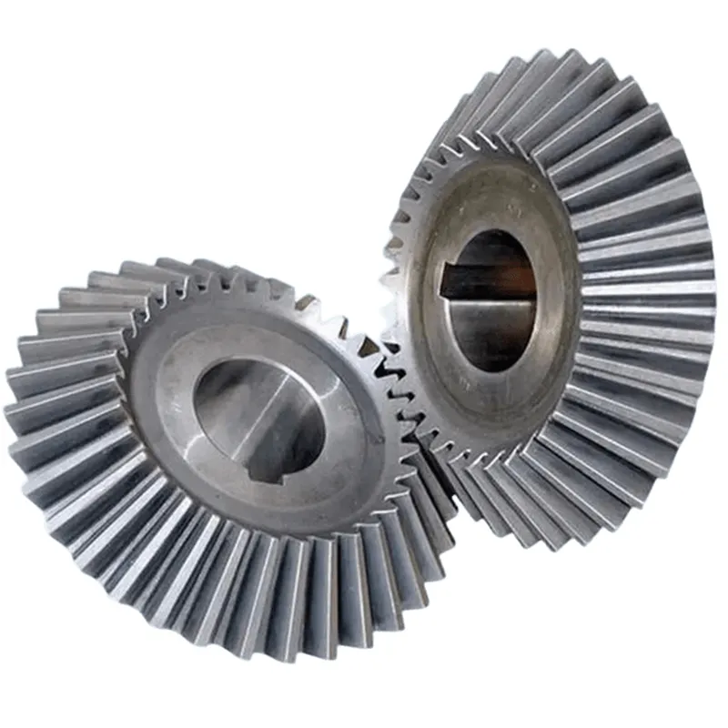
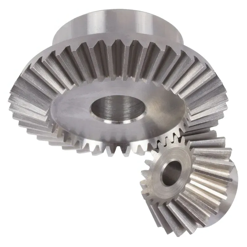
A. 直齿锥齿轮
直齿锥齿轮的齿是直的,呈圆锥形。测量时 直齿锥齿轮请密切注意以下参数:
- 节圆直径:在后锥距处测量节圆直径。此处是大齿轮与其啮合小齿轮啮合的位置。使用游标卡尺或千分尺进行精确测量。
- 齿厚:检查齿在正常截面处的厚度。该厚度是在标准节圆上测量的。齿轮齿厚游标卡尺是进行此项测量的首选工具。
- 后锥距:这是锥体中心到齿轮背面的距离。这是一个影响齿轮对准的关键尺寸。可以使用深度千分尺或坐标测量机 (CMM) 进行测量。
- 齿面角:齿锥与齿轮背面所成的角度称为齿面角。该角度可用锥角规或三坐标测量机 (CMM) 测量。请确认其与设计角度相符。
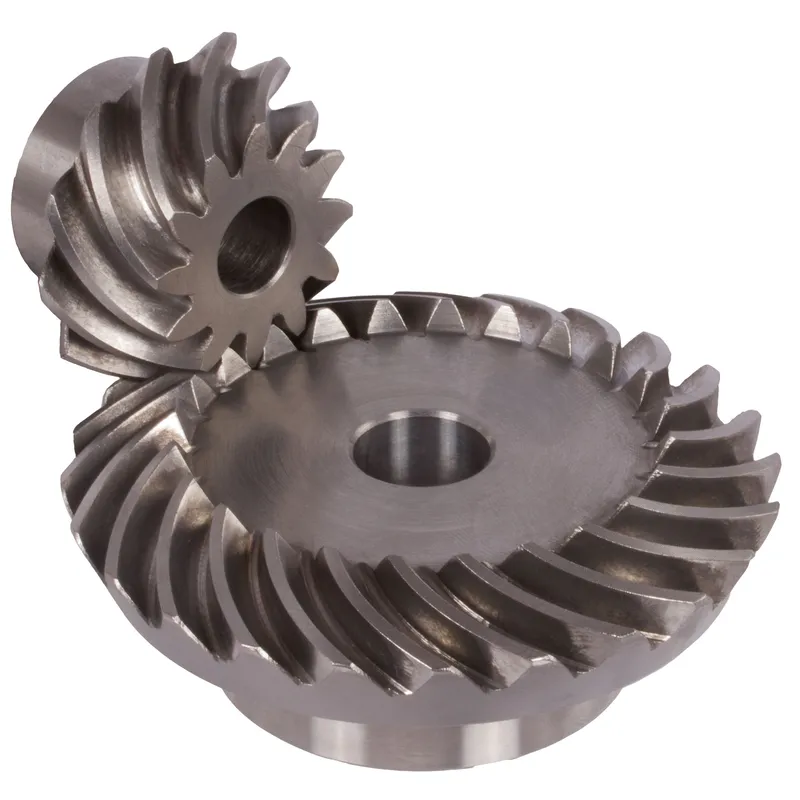
B. 螺旋锥齿轮
螺旋锥齿轮的齿呈弧形,沿锥面斜线排列。检查螺旋锥齿轮的关键尺寸包括:
- 平均螺旋角:这是齿迹与穿过齿迹中心的节锥面元素之间的夹角。它是在平均锥距处测量的。为了获得可靠的测量结果,请使用配备分度头的螺旋锥齿轮试验机。
- 压力角:压力角 螺旋锥齿轮 压力角是在平均点处测量的。它定义为垂直于齿面的直线与切于节面的平面之间的夹角。齿轮测量机上的专用刀具需要用于精确测量压力角。
- 节圆顶点至齿冠:这是轴向平面内节圆顶点到齿冠的距离。齿冠是两个啮合螺旋锥齿轮中较大的一个。可以使用深度千分尺直接测量。
C. 准双曲面和零曲面锥齿轮
准双曲面齿轮和零度锥齿轮是特殊的螺旋锥齿轮。准双曲面齿轮的小齿轮和大齿轮轴线之间存在偏移,而零度锥齿轮的偏移量为零。测量这些齿轮类型时,应重点关注:
- 节圆顶点至齿冠:与螺旋锥齿轮类似,该尺寸对于正确的装配和运行至关重要。使用深度规测量齿根端到节圆顶点的距离。
- 偏移量:对于准双曲面齿轮,小齿轮轴线相对于大齿轮轴线存在上下偏移。这种偏移量会影响齿轮啮合,必须严格控制。可以使用准双曲面齿轮试验机来测量偏移量,该试验机可以模拟齿轮和小齿轮的实际工作位置。
- 螺旋角:准双曲面齿轮和零度齿轮的齿形均为螺旋形。螺旋角定义于这些齿轮类型的平均点。与螺旋锥齿轮一样,使用带有分度头的螺旋锥齿轮测试仪来测量此参数。