Sistem Gigi Lurus Nisbah Gear Serong Keluli Tahan Karat 4:1
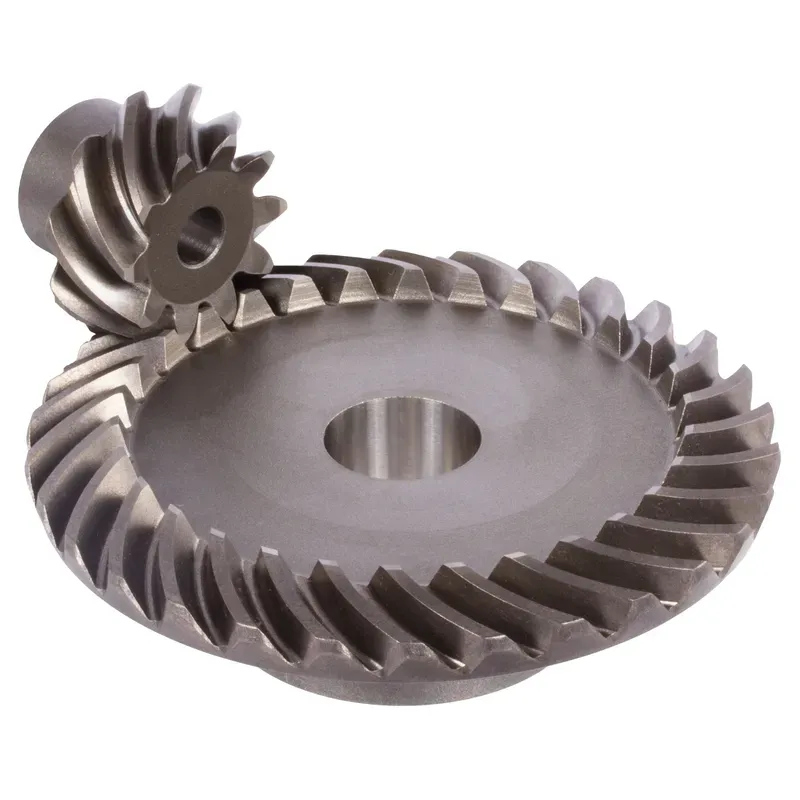
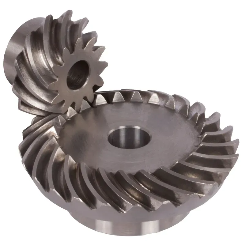
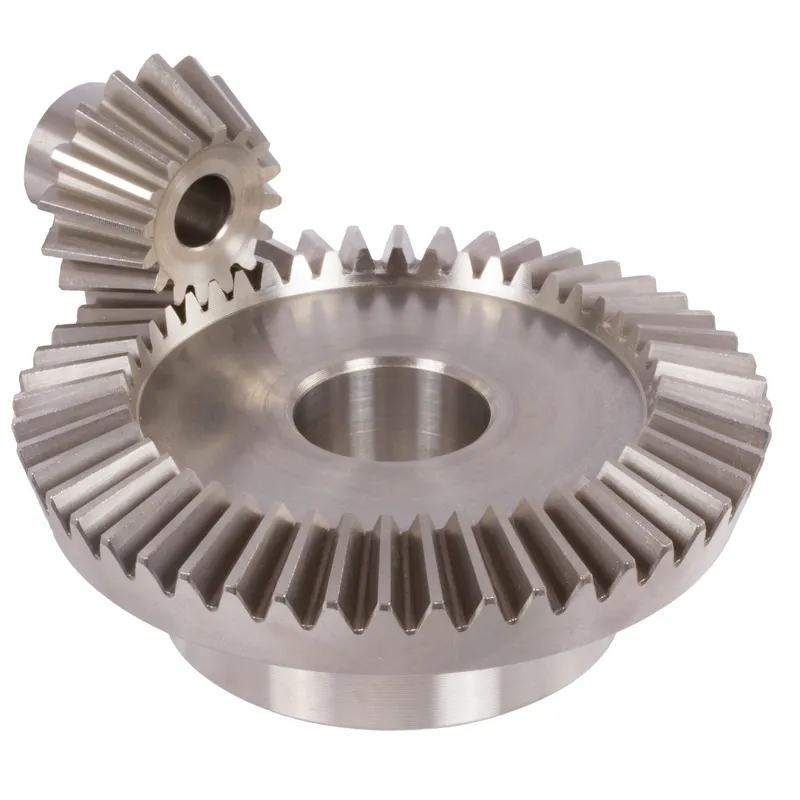
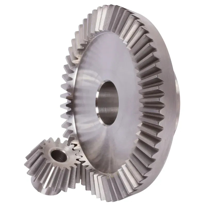
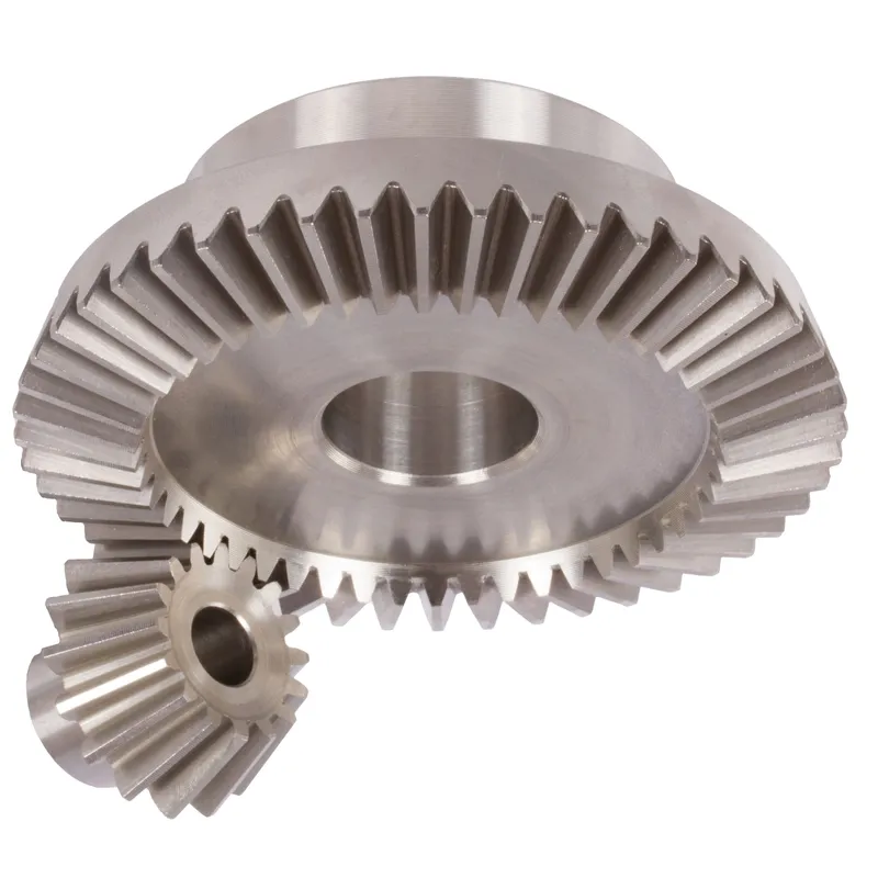
Sistem gear serong keluli tahan karat nisbah gigi lurus 4:1 ialah persediaan gear mekanikal yang direka untuk penghantaran kuasa yang cekap antara dua aci bersilang, biasanya pada sudut tepat (90°). Gear serong ini diperbuat daripada keluli tahan karat yang tahan lama, menawarkan rintangan yang sangat baik terhadap kakisan, haus dan persekitaran suhu tinggi, menjadikannya sesuai untuk aplikasi perindustrian yang mencabar.
Sistem gear serong keluli tahan karat nisbah gigi lurus 4:1 ialah persediaan gear mekanikal yang direka untuk penghantaran kuasa yang cekap antara dua aci bersilang, biasanya pada sudut tepat (90°). Gear serong ini diperbuat daripada keluli tahan karat yang tahan lama, menawarkan rintangan yang sangat baik terhadap kakisan, haus dan persekitaran suhu tinggi, menjadikannya sesuai untuk aplikasi perindustrian yang mencabar.
Istilah nisbah 4:1 menunjukkan bahawa gear yang lebih kecil (pinion) melengkapkan empat pusingan untuk setiap satu pusingan gear yang lebih besar. Ini membolehkan pengurangan kelajuan yang ketara sambil menguatkan tork. Reka bentuk gigi lurus merujuk kepada gigi gear linear yang tersusun secara jejari, yang lebih mudah dibuat dan diselaraskan berbanding gear serong lingkaran. Walaupun sedikit lebih bising disebabkan oleh penglibatan gigi yang mendadak, ia sesuai untuk aplikasi kelajuan rendah hingga sederhana di mana ketepatan dan ketahanan adalah penting.
Nisbah Gear Serong Keluli Tahan Karat 4:1
| 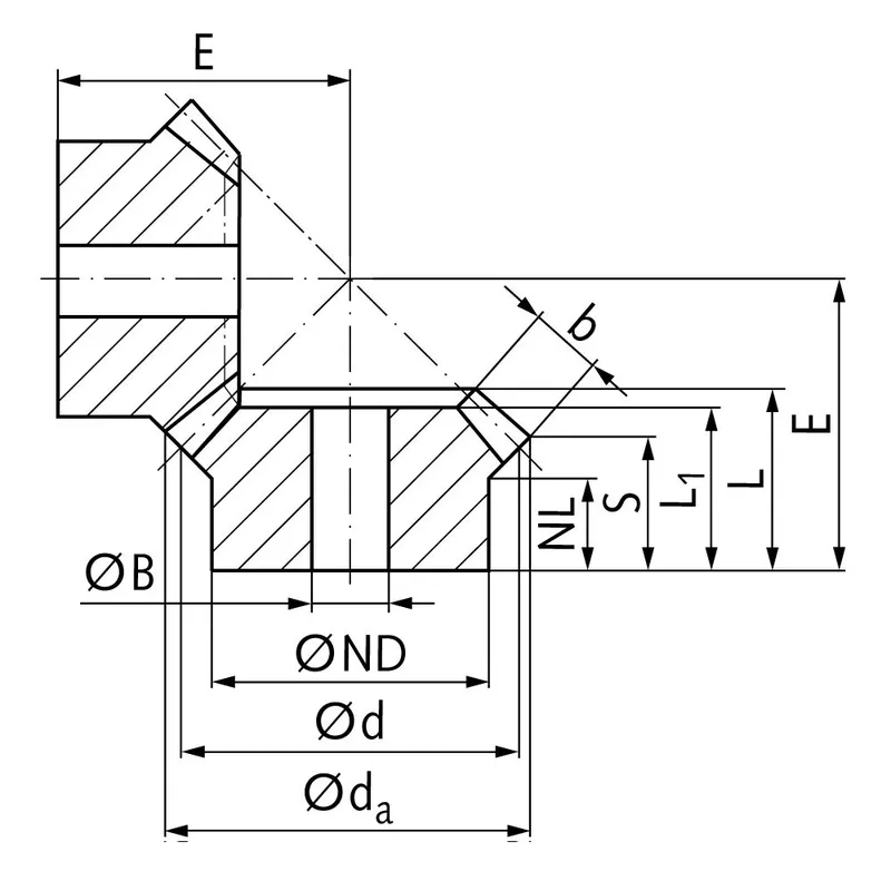 |
| Modul | Nombor gigi | dseorang | d | ND | NL | L1 | L | S | b | BH7 | E | Tork* | Berat |
| mm | mm | mm | mm | mm | mm | mm | mm | mm | mm | Ncm | g | ||
| 1 | 15 | 17,8 | 15 | 13 | 7,7 | 17,3 | 17,3 | 8,4 | 9,3 | 5 | 38 | 0,14 | 15 |
| 1 | 60 | 60,3 | 60 | 30 | 10,0 | 15 | 17,1 | 15,1 | 9,3 | 8 | 22 | 0,56 | 160 |
| 1,5 | 15 | 26,7 | 22,5 | 18 | 14,45 | 28 | 28,9 | 15,5 | 13,9 | 8 | 60 | 0,48 | 42 |
| 1,5 | 60 | 90,4 | 90 | 50 | 12,0 | 25 | 27,6 | 24,6 | 13,9 | 15 | 35 | 1,92 | 745 |
| 2 | 15 | 34,0 | 30 | 20 | 13,5 | 29 | 29,9 | 15,5 | 15 | 10 | 75 | 1,34 | 80 |
| 2 | 60 | 120,9 | 120 | 60 | 20,0 | 35 | 40,1 | 37,0 | 15 | 25 | 50 | 5,36 | 1600 |
| 2,5 | 15 | 42,5 | 37,5 | 30 | 16,1 | 35 | 36,8 | 17,6 | 20 | 10 | 92 | 2,5 | 190 |
| 2,5 | 60 | 151,2 | 150 | 80 | 18,0 | 33 | 37,8 | 33,8 | 20 | 25 | 50 | 10,0 | 2600 |
| 3 | 15 | 51,0 | 45 | 30 | 13,15 | 38 | 39,7 | 15,7 | 25 | 10 | 105 | 4,4 | 270 |
| 3 | 60 | 181,5 | 180 | 80 | 18,0 | 35 | 40,6 | 35,5 | 25 | 30 | 55 | 17,6 | 3800 |
| 4 | 15 | 68,0 | 60 | 40 | 12,5 | 43 | 44,8 | 16,0 | 30 | 20 | 135 | 8,9 | 520 |
| 4 | 60 | 242,0 | 240 | 90 | 20,0 | 41 | 50,1 | 44,0 | 30 | 30 | 70 | 35,6 | 8300 |
Kelebihan Gear Serong Keluli Tahan Karat
Kapasiti Tork Tinggi
Salah satu kelebihan utama gear serong keluli tahan karat ialah keupayaannya untuk mengendalikan beban tork yang tinggi. Geometri dan reka bentuk gear serong membolehkan penghantaran kuasa dan tork yang cekap antara aci yang bersilang.
Reka Bentuk Kompak
Gear serong menawarkan penyelesaian padat untuk penghantaran kuasa antara aci bukan selari. Dengan menggunakan geometri kon, gear serong boleh mengubah arah putaran secara berkesan dalam ruang terhad.
Operasi Lancar dan Senyap
Apabila direka bentuk dan dihasilkan dengan betul, gear serong boleh memberikan operasi yang lancar dan senyap. Kemajuan dalam geometri gigi gear, seperti penggunaan gear serong lingkaran dan gear hipoid, telah meningkatkan keupayaan kelancaran dan pengurangan hingar gear serong dengan ketara. Profil gigi melengkung gear serong lingkaran membolehkan penglibatan dan pelepasan secara beransur-ansur, menghasilkan operasi yang lebih senyap berbanding gear serong lurus.
Kebolehgunaan dalam Sudut Aci
Gear serong menawarkan fleksibiliti dari segi sudut aci yang boleh ditampungnya. Walaupun sudut aci yang paling biasa untuk gear serong ialah 90 darjah, ia boleh direka bentuk untuk berfungsi dengan pelbagai sudut aci.
Kelemahan Gear Serong Keluli Tahan Karat
Kerumitan Pembuatan yang Lebih Tinggi
Salah satu kelemahan utama gear serong keluli tahan karat ialah kerumitan pembuatannya yang lebih tinggi berbanding jenis gear lain, seperti gear taji. Pengeluaran gear serong memerlukan jentera khusus dan proses pembuatan yang tepat untuk mencapai geometri gigi dan kemasan permukaan yang diingini. Kerumitan ini boleh mengakibatkan peningkatan kos pembuatan dan masa tunggu yang lebih lama.
Kepekaan terhadap Ketidaksejajaran
Gear serong lebih sensitif terhadap ketidaksejajaran berbanding jenis gear lain. Ketidaksejajaran boleh menyebabkan pengagihan beban yang tidak sekata, peningkatan tekanan pada gigi gear dan kegagalan pramatang.
Keupayaan Kelajuan Terhad
Gear serong mempunyai batasan dari segi keupayaan kelajuannya. Pada kelajuan tinggi, gear serong terdedah kepada bunyi bising dan getaran yang berlebihan disebabkan oleh tindakan gelongsor antara gigi gear. Ini boleh menyebabkan kecekapan yang berkurangan dan haus yang meningkat. Akibatnya, gear serong biasanya digunakan dalam aplikasi dengan keperluan kelajuan sederhana hingga rendah.
Kos Lebih Tinggi
Kerumitan dan ketepatan pembuatan yang diperlukan untuk gear serong selalunya diterjemahkan kepada kos yang lebih tinggi berbanding jenis gear yang lebih mudah. Keperluan untuk jentera khusus, buruh mahir dan langkah kawalan kualiti yang ketat menyumbang kepada peningkatan kos gear serong. Di samping itu, penyesuaian dan keperluan reka bentuk khusus gear serong untuk aplikasi tertentu boleh meningkatkan lagi kosnya.
Apakah Gear Serong Digunakan Untuk
Penghantaran Kuasa dalam Automobil
Gear serong banyak digunakan dalam industri automotif, terutamanya dalam pemacu pembezaan. Dalam pembezaan, gear serong lurus digunakan untuk memisahkan kuasa daripada aci pemacu dan menghantarnya ke roda sambil membolehkannya berputar pada kelajuan yang berbeza. Ini membolehkan pembelokkan yang lancar dan kawalan cengkaman yang lebih baik. Gear serong juga digunakan dalam pelbagai aplikasi automotif lain, seperti kotak pemindahan dan sistem stereng.
Jentera Perindustrian
Gear serong biasanya digunakan dalam jentera perindustrian di mana kuasa perlu dihantar antara aci yang bersilang. Ia terdapat dalam pelbagai peralatan, termasuk kotak gear, pengurang kelajuan dan sistem penghantaran kuasa. Aplikasi perindustrian yang menggunakan gear serong termasuk jentera perlombongan, peralatan pembinaan, mesin cetak dan jentera tekstil.
Aeroangkasa dan Penerbangan
Industri aeroangkasa dan penerbangan bergantung pada gear serong keluli tahan karat untuk penghantaran kuasa dalam pelbagai aplikasi. Gear serong digunakan dalam enjin pesawat, sistem pemacu rotor dan kotak gear aksesori. Ia direka bentuk untuk mengendalikan beban tinggi dan memberikan prestasi yang andal dalam keadaan operasi yang mencabar. Reka bentuk yang padat dan keupayaan untuk menghantar kuasa antara aci bukan selari menjadikan gear serong sesuai untuk aplikasi aeroangkasa di mana ruang terhad.
Aplikasi Marin
Gear serong digunakan dalam aplikasi marin untuk penghantaran kuasa dalam sistem pendorongan, sistem stereng dan jentera dek. Ia digunakan dalam kotak gear marin, pendorong dan win. Keupayaan gear serong untuk mengendalikan beban tork yang tinggi dan menahan persekitaran marin yang keras menjadikannya sesuai untuk aplikasi ini. Gear serong marin selalunya diperbuat daripada bahan tahan kakisan untuk memastikan ketahanan dan kebolehpercayaan.
 |  |
| Gear Serong untuk Pembezaan Automotif | Gear Serong untuk Jentera Industri |
 |  |
| Gear Serong untuk Robotik | Gear Serong untuk Industri Marin |
Pengukuran Gear Serong Keluli Tahan Karat
Langkah 1: Kumpulkan Alat dan Peralatan yang Diperlukan
Untuk mengukur gear serong dengan tepat, anda memerlukan alat berikut:
- Angkup atau mikrometer vernier untuk mengukur ketebalan, kedalaman, dan diameter gigi
- Protraktor serong untuk mengukur sudut pic dan akar
- Angkup vernier gigi gear untuk mengukur ketebalan gigi pada kedalaman tertentu
- Plat permukaan dan tolok ketinggian untuk memeriksa larian gear dan jarak pemasangan
Langkah 2: Ukur Diameter Pitch
Untuk mengukur diameter pic:
- Letakkan gear serong pada plat permukaan dengan bahagian belakang menghadap ke bawah.
- Letakkan tolok ketinggian serenjang dengan plat permukaan dan sejajarkan hujung pengukurnya dengan garis pic pada rusuk gigi gear.
- Sifarkan tolok ketinggian pada kedudukan ini.
- Putar gear 180 darjah dan ukur ketinggian pada garisan pic yang sepadan pada sisi gigi yang bertentangan.
- Diameter padang dikira dengan menambah dua ukuran ketinggian.
Ulangi proses ini pada berbilang gigi di sekeliling gear untuk memastikan konsistensi dan semak potensi masalah larian.
Langkah 3: Ukur Ketebalan Gigi
Untuk mengukur ketebalan gigi:
- Gunakan angkup vernier gigi gear yang diletakkan pada garisan pic.
- Ukur ketebalan gigi pada garisan gelincir, berhati-hati agar tidak merosakkan profil gigi.
- Ulangi ukuran ini pada beberapa gigi di sekeliling gear, perhatikan sebarang variasi.
Secara alternatif, angkup vernier atau mikrometer standard boleh digunakan untuk mengukur ketebalan korda di pangkal gigi.
Langkah 4: Ukur Tekanan dan Sudut Akar
Untuk mengukur sudut-sudut ini:
- Letakkan protraktor serong pada kon pic gear, sejajarkan tepinya dengan rusuk gigi.
- Baca sudut tekanan terus dari skala protraktor pada titik ketangensi dengan profil gigi.
- Letakkan semula protraktor agar sejajar dengan garis akar gigi untuk mengukur sudut akar.
Sahkan bahawa sudut yang diukur sepadan dengan parameter reka bentuk gear yang ditentukan.
Langkah 5: Periksa Larian Gear
Larian gear merujuk kepada variasi dalam geometri gear apabila ia berputar pada paksinya. Untuk memeriksa larian gear:
- Pasangkan gear serong pada mandrel atau arbor yang disokong oleh blok-V pada plat permukaan.
- Letakkan penunjuk dail dengan probnya menyentuh permukaan belakang gear berhampiran diameter luar.
- Putar gear perlahan-lahan, perhatikan bacaan penunjuk jumlah (TIR) pada dail.
- Bandingkan TIR yang diukur dengan toleransi yang ditentukan untuk larian keluar.
Ulangi proses ini di bahagian hadapan gear dan pada diameter pic untuk menilai sepenuhnya larian gear.
Langkah 6: Sahkan Jarak Pemasangan
Jarak pemasangan ialah kedudukan paksi gear serong berbanding gear padanannya. Untuk mengesahkan jarak pemasangan:
- Letakkan gear serong pada plat permukaan dengan bahagian hadapannya menghadap ke bawah.
- Gunakan tolok ketinggian untuk mengukur jarak dari plat permukaan ke permukaan belakang gear pada jejari jarak pemasangan yang ditentukan.
- Bandingkan ukuran ini dengan jarak pemasangan yang direka bentuk untuk gear.
Maklumat tambahan
| Disunting oleh | Yjx |
|---|