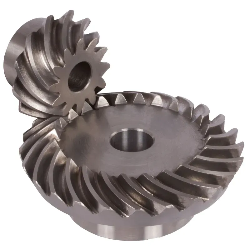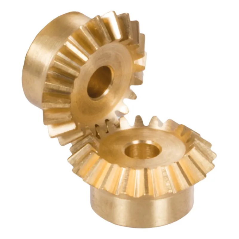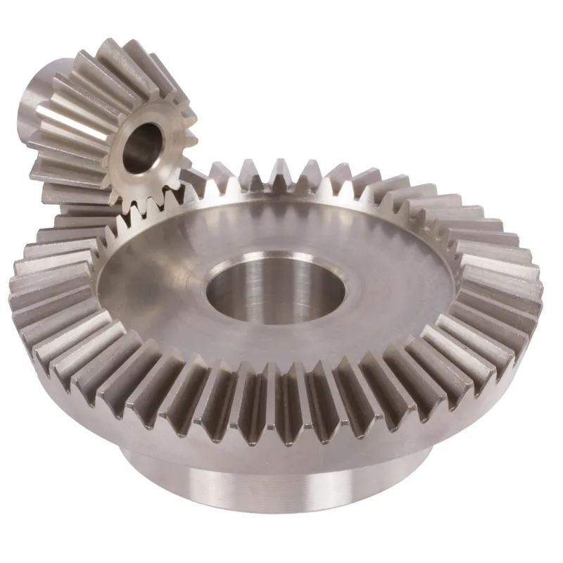
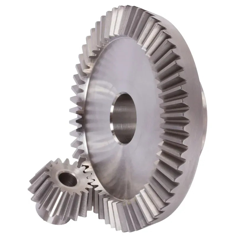
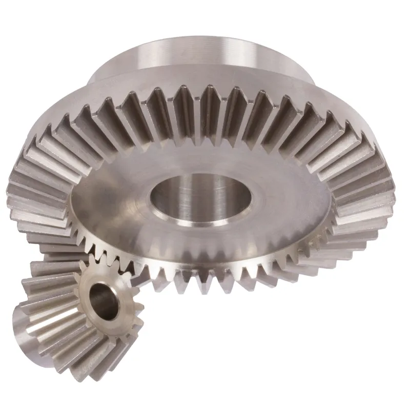
ステンレススチール製ベベルギア比4:1ストレート歯システム
ステンレス鋼製の4:1ストレート歯ベベルギアシステムは、通常90°の直角で交差する2本のシャフト間で効率的な動力伝達を行うために設計された機械式ギアシステムです。これらのベベルギアは耐久性の高いステンレス鋼で作られており、腐食、摩耗、高温環境に対する優れた耐性を備えているため、要求の厳しい産業用途に適しています。
ステンレス鋼製の4:1ストレート歯ベベルギアシステムは、通常90°の直角で交差する2本のシャフト間で効率的な動力伝達を行うために設計された機械式ギアシステムです。これらのベベルギアは耐久性の高いステンレス鋼で作られており、腐食、摩耗、高温環境に対する優れた耐性を備えているため、要求の厳しい産業用途に適しています。
4:1の比率とは、大きい方のギアが1回転する間に、小さい方のギア(ピニオン)が4回転することを意味します。これにより、速度を大幅に減速しながらトルクを増幅することができます。ストレート歯設計とは、直線状に放射状に配置された歯を持つギアのことで、スパイラルベベルギアに比べて製造や位置合わせが容易です。歯のかみ合いが急激なため、若干騒音は大きくなりますが、精度と耐久性が不可欠な低速から中速の用途に最適です。
ステンレス製ベベルギア、ギア比4:1
| 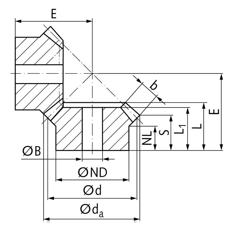 |
| モジュール | 番号 歯の | d1つの | d | ND | オランダ | L1 | L | S | b | BH7 | E | トルク* | 重さ |
| んん | んん | んん | んん | んん | んん | んん | んん | んん | んん | Ncm | グラム | ||
| 1 | 15 | 17,8 | 15 | 13 | 7,7 | 17,3 | 17,3 | 8,4 | 9,3 | 5 | 38 | 0,14 | 15 |
| 1 | 60 | 60,3 | 60 | 30 | 10,0 | 15 | 17,1 | 15,1 | 9,3 | 8 | 22 | 0,56 | 160 |
| 1,5 | 15 | 26,7 | 22,5 | 18 | 14,45 | 28 | 28,9 | 15,5 | 13,9 | 8 | 60 | 0,48 | 42 |
| 1,5 | 60 | 90,4 | 90 | 50 | 12,0 | 25 | 27,6 | 24,6 | 13,9 | 15 | 35 | 1,92 | 745 |
| 2 | 15 | 34,0 | 30 | 20 | 13,5 | 29 | 29,9 | 15,5 | 15 | 10 | 75 | 1,34 | 80 |
| 2 | 60 | 120,9 | 120 | 60 | 20,0 | 35 | 40,1 | 37,0 | 15 | 25 | 50 | 5,36 | 1600 |
| 2,5 | 15 | 42,5 | 37,5 | 30 | 16,1 | 35 | 36,8 | 17,6 | 20 | 10 | 92 | 2,5 | 190 |
| 2,5 | 60 | 151,2 | 150 | 80 | 18,0 | 33 | 37,8 | 33,8 | 20 | 25 | 50 | 10,0 | 2600 |
| 3 | 15 | 51,0 | 45 | 30 | 13,15 | 38 | 39,7 | 15,7 | 25 | 10 | 105 | 4,4 | 270 |
| 3 | 60 | 181,5 | 180 | 80 | 18,0 | 35 | 40,6 | 35,5 | 25 | 30 | 55 | 17,6 | 3800 |
| 4 | 15 | 68,0 | 60 | 40 | 12,5 | 43 | 44,8 | 16,0 | 30 | 20 | 135 | 8,9 | 520 |
| 4 | 60 | 242,0 | 240 | 90 | 20,0 | 41 | 50,1 | 44,0 | 30 | 30 | 70 | 35,6 | 8300 |
ステンレス鋼製ベベルギアの利点
高トルク容量
ステンレス鋼製ベベルギアの主な利点の1つは、高トルク負荷に対応できることです。ベベルギアの形状と設計により、交差するシャフト間で動力とトルクを効率的に伝達できます。
コンパクト設計
ベベルギアは、平行でない軸間での動力伝達において、コンパクトなソリューションを提供します。円錐形状を利用することで、ベベルギアは限られたスペース内で回転方向を効果的に変更できます。
スムーズで静かな操作
適切に設計・製造されたベベルギアは、滑らかで静かな動作を実現します。スパイラルベベルギアやハイポイドギアなどの歯形形状の改良により、ベベルギアの滑らかさと騒音低減性能は大幅に向上しました。スパイラルベベルギアの湾曲した歯形は、噛み合いと噛み合い解除を緩やかに行うことができ、直線状のベベルギアに比べて静かな動作を実現します。
シャフト角度の多様性
ベベルギアは、対応できる軸角度に関して柔軟性があります。ベベルギアの最も一般的な軸角度は90度ですが、さまざまな軸角度に対応できるように設計できます。
ステンレス鋼製ベベルギアの欠点
製造工程の複雑化
ステンレス鋼製ベベルギアの主な欠点の1つは、平歯車などの他のタイプの歯車に比べて製造工程が複雑であることです。ベベルギアの製造には、所望の歯形と表面仕上げを実現するために、特殊な機械と精密な製造プロセスが必要です。この複雑さにより、製造コストの増加と納期の長期化につながる可能性があります。
位置ずれに対する感度
ベベルギアは、他の種類のギアに比べて、位置ずれの影響を受けやすい。位置ずれは、荷重分布の不均一、歯への応力増加、そして早期破損につながる可能性がある。
速度制限機能
ベベルギアは、回転速度の面で限界があります。高速回転時には、歯間の滑りによって過剰な騒音や振動が発生しやすくなります。これは効率の低下や摩耗の増加につながります。そのため、ベベルギアは通常、中速から低速の用途で使用されます。
コスト増
ベベルギアは、製造工程の複雑さと高い精度が求められるため、よりシンプルなギアに比べてコストが高くなる傾向があります。特殊な機械設備、熟練した作業員、そして厳格な品質管理体制が必要となることが、ベベルギアのコスト上昇の一因となっています。さらに、特定の用途に合わせたカスタマイズや設計要件も、コスト増につながる可能性があります。
ベベルギアは何に使われるのか
自動車における動力伝達
ベベルギアは自動車産業、特に差動装置において幅広く使用されています。差動装置では、ストレートベベルギアがドライブシャフトからの動力を分割し、車輪に伝達する際に、それぞれの車輪が異なる速度で回転できるようにします。これにより、スムーズなコーナリングとトラクションコントロールの向上が可能になります。ベベルギアは、トランスファーケースやステアリングシステムなど、その他の様々な自動車用途にも使用されています。
産業機械
ベベルギアは、交差するシャフト間で動力を伝達する必要がある産業機械で一般的に使用されています。ギアボックス、減速機、動力伝達システムなど、幅広い機器に用いられています。ベベルギアが利用されている産業用途としては、鉱山機械、建設機械、印刷機、繊維機械などが挙げられます。
航空宇宙および航空
航空宇宙産業では、様々な用途における動力伝達にステンレス鋼製ベベルギアが広く用いられています。ベベルギアは、航空機エンジン、ローター駆動システム、および補助ギアボックスなどに使用されています。高負荷に対応し、過酷な運転条件下でも信頼性の高い性能を発揮するように設計されています。コンパクトな設計と、平行でないシャフト間での動力伝達能力により、ベベルギアはスペースが限られた航空宇宙用途に最適です。
海洋用途
ベベルギアは、船舶用途において、推進システム、操舵システム、甲板機械などの動力伝達に用いられます。船舶用ギアボックス、スラスタ、ウインチなどに使用されています。ベベルギアは高トルク負荷に対応でき、過酷な海洋環境にも耐えられるため、これらの用途に適しています。船舶用ベベルギアは、耐久性と信頼性を確保するため、耐腐食性材料で製造されることがよくあります。
 |  |
| 自動車用デファレンシャル用ベベルギア | 産業機械用ベベルギア |
 |  |
| ロボット用ベベルギア | 海洋産業向けベベルギア |
ステンレス鋼ベベルギア測定
ステップ1:必要な道具と設備を揃える
ベベルギアを正確に測定するには、以下の工具が必要です。
- 歯の厚さ、深さ、ピッチ径を測定するためのノギスまたはマイクロメーター
- ピッチ角とルート角を測定するためのベベル分度器
- 特定の深さにおける歯の厚さを測定するための歯車歯用ノギス
- ギアの振れと取り付け距離を確認するための定盤と高さゲージ
ステップ2:ピッチ径を測定する
ピッチ径を測定するには:
- ベベルギアを裏面を下にして定盤の上に置いてください。
- ハイトゲージを定盤に対して垂直に配置し、測定先端を歯車の歯面上のピッチ線に合わせます。
- この位置で高さ計をゼロに調整してください。
- ギアを180度回転させ、反対側の歯面にある対応するピッチ線の高さを測定します。
- ピッチ径は、2つの高さ測定値を合計することで算出されます。
ギアの複数の歯に対してこのプロセスを繰り返し、一貫性を確保するとともに、振れなどの潜在的な問題がないか確認してください。
ステップ3:歯の厚さを測定する
歯の厚さを測定するには:
- ピッチ線に歯車歯目盛付きノギスを配置して使用します。
- 歯のピッチラインに沿って歯の厚さを測定します。その際、歯の形状を損なわないように注意してください。
- ギアの周囲の複数の歯でこの測定を繰り返し、変化があれば記録してください。
あるいは、標準的なノギスやマイクロメーターを用いて、歯の根元の弦の厚さを測定することもできる。
ステップ4:圧力と根角を測定する
これらの角度を測定するには:
- ベベル分度器を歯車のピッチコーンに置き、その端を歯面に合わせる。
- 歯面との接点における圧力角を、分度器の目盛りから直接読み取ってください。
- 歯根の角度を測定するために、分度器を歯根線に合わせるように位置を調整します。
測定された角度が、指定されたギア設計パラメータと一致していることを確認してください。
ステップ5:ギアの振れを検査する
ギアの振れとは、ギアが軸を中心に回転する際のギア形状のばらつきを指します。振れを確認するには:
- ベベルギアを、定盤上のVブロックで支持されたマンドレルまたはアーバーに取り付ける。
- ダイヤルゲージのプローブを、歯車の背面、外径付近に接触させるように配置します。
- ギアをゆっくりと回転させ、ダイヤル上のトータルインジケーターの読み値(TIR)を確認します。
- 測定されたTIRを、規定された振れ許容値と比較してください。
ギアの振れを完全に評価するために、この手順をギアの前面とピッチ径で繰り返してください。
ステップ6:取り付け距離を確認する
取付距離とは、ベベルギアと相手ギアとの軸方向の位置関係のことです。取付距離を確認するには:
- ベベルギアを、前面を下にして定盤の上に置く。
- 高さゲージを使用して、指定された取り付け距離半径における、定盤からギアの背面までの距離を測定します。
- この測定値を、ギアの設計上の取り付け距離と比較してください。
追加情報
| 編集者 | Yjx |
|---|