Inaccurate bevel gear measurements lead to poor performance, premature failures, and costly rework in machinery applications. Imprecise dimensions and deviations from gear standards result in noisy operation, reduced power transmission efficiency, and alignment issues that can bring production lines to a halt.
Dimensioni e angoli chiave degli ingranaggi conici
Gli ingranaggi conici sono componenti meccanici complessi caratterizzati da una gamma di dimensioni e angoli critici.
A. Esame dettagliato delle dimensioni di base
Diverse dimensioni chiave definiscono la geometria complessiva e le dimensioni di un ingranaggio conico:
- Diametro del passo: This diameter is measured at the heel end of the bevel gear teeth. It represents the effective size of the gear and is a fundamental parameter for gear calculations and design.
- Angolo del cono di inclinazione: L'angolo del cono primitivo descrive l'angolo formato dal cono primitivo rispetto all'asse dell'ingranaggio. Definisce l'orientamento dei denti dell'ingranaggio e determina il modo in cui l'ingranaggio si innesta con il suo pignone di accoppiamento.
- Addendum e Dedendum: L'addendum è l'altezza del dente dell'ingranaggio sopra il cono primitivo, mentre il dedendum è la profondità al di sotto di esso. Insieme, definiscono la profondità totale del dente. L'addendum e il dedendum sono in genere specificati in proporzione al modulo dell'ingranaggio.
- Larghezza del viso: La larghezza della faccia si riferisce alla dimensione del dente dell'ingranaggio misurata lungo la generatrice del cono primitivo dal tallone alla punta. Influisce sulla resistenza del dente dell'ingranaggio e sulla capacità di carico. Larghezze della faccia maggiori generalmente consentono una maggiore trasmissione della coppia.
- Distanza del cono: La distanza conica rappresenta la distanza tra l'apice del cono primitivo e la faccia centrale dell'ingranaggio conico. È una dimensione fondamentale per il posizionamento dell'ingranaggio rispetto al suo pignone di accoppiamento durante l'assemblaggio.
- Distanza del vertice: La distanza al vertice misura lo scostamento dall'asse dell'ingranaggio all'apice del cono primitivo. Aiuta a individuare il punto teorico di accoppiamento tra gli ingranaggi.
B. Angoli essenziali degli ingranaggi conici
Oltre alle dimensioni lineari, diversi angoli sono fondamentali per definire la geometria di un ingranaggio conico:
- Angolo del viso: Angolo tra la generatrice del cono frontale e l'asse dell'ingranaggio. Determina l'angolo delle estremità esterne dei denti dell'ingranaggio rispetto all'asse di rotazione.
- Angolo del bordo: Misurato tra la generatrice del cono esterno e l'asse dell'ingranaggio, l'angolo del bordo definisce la pendenza delle estremità interne dei denti più vicini all'apice.
- Angolo di addendum: Questo è l'equivalente angolare dell'addendum, che definisce l'altezza del dente in termini angolari dall'angolo della faccia al bordo esterno.
- Angolo di Dedendum: Di conseguenza, l'angolo dedendum misura la profondità angolare del dente dalla linea primitiva fino alla radice del dente.
C. Contraccolpo
Il gioco si riferisce al gioco tra i denti di due ingranaggi in presa. Un certo gioco è necessario per consentire la lubrificazione, le tolleranze di fabbricazione e l'espansione termica. Tuttavia, un gioco eccessivo può causare rumore, vibrazioni e posizionamento impreciso. Il gioco viene in genere misurato nel punto di massima ingranamento utilizzando strumenti dedicati o valutando il gioco angolare con gli ingranaggi mantenuti fissi.
Modulo D.
Il modulo di un ingranaggio è un'unità di misura standardizzata che indica la dimensione dei denti. È definito come il rapporto tra il diametro primitivo e il numero di denti. Negli ingranaggi conici, il modulo viene solitamente specificato all'estremità del tallone per scopi di produzione. Numeri di modulo più grandi corrispondono a denti più grandi e più grossi, mentre gli ingranaggi a passo più fine hanno moduli più piccoli.
Measuring Bevel Gears Step by Step
Step 1: Gather Required Tools and Equipment
To accurately measure bevel gears, you will need the following tools:
- Vernier caliper or micrometer for measuring tooth thickness, depth, and pitch diameter
- Bevel protractor for measuring pitch and root angles
- Gear tooth vernier caliper for measuring tooth thickness at a specific depth
- Surface plate and height gauge for checking gear runout and mounting distance
Step 2: Measure Pitch Diameter
To measure pitch diameter:
- Place the bevel gear on a surface plate with the back face down.
- Position the height gauge perpendicular to the surface plate and align its measuring tip with the pitch line on a gear tooth flank.
- Zero the height gauge at this position.
- Rotate the gear 180 degrees and measure the height at the corresponding pitch line on the opposite tooth flank.
- The pitch diameter is calculated by adding the two height measurements.
Repeat this process on multiple teeth around the gear to ensure consistency and check for potential runout issues.
Step 3: Measure Tooth Thickness
To measure tooth thickness:
- Use a gear tooth vernier caliper positioned at the pitch line.
- Measure the thickness of a tooth at the pitch line, taking care not to damage the tooth profile.
- Repeat this measurement on several teeth around the gear, noting any variations.
Alternatively, a standard vernier caliper or micrometer can be used to measure the chordal thickness at the base of the tooth.
Step 4: Measure Pressure and Root Angles
To measure these angles:
- Place the bevel protractor on the pitch cone of the gear, aligning its edge with a tooth flank.
- Read the pressure angle directly from the protractor scale at the point of tangency with the tooth profile.
- Reposition the protractor to align with the root line of the tooth to measure the root angle.
Verify that the measured angles match the specified gear design parameters.
Step 5: Inspect Gear Runout
Gear runout refers to the variation in gear geometry as it rotates about its axis. To check runout:
- Mount the bevel gear on a mandrel or arbor supported by V-blocks on a surface plate.
- Position a dial indicator with its probe contacting the back face of the gear near the outer diameter.
- Slowly rotate the gear, noting the total indicator reading (TIR) on the dial.
- Compare the measured TIR to the specified tolerance for runout.
Repeat this process at the front face of the gear and at the pitch diameter to fully evaluate gear runout.
Step 6: Verify Mounting Distance
The mounting distance is the axial position of the bevel gear relative to its mating gear. To verify mounting distance:
- Place the bevel gear on a surface plate with its front face down.
- Use a height gauge to measure the distance from the surface plate to the back face of the gear at the specified mounting distance radius.
- Compare this measurement to the gear’s designed mounting distance.

Specific Considerations for Different Bevel Gear Types
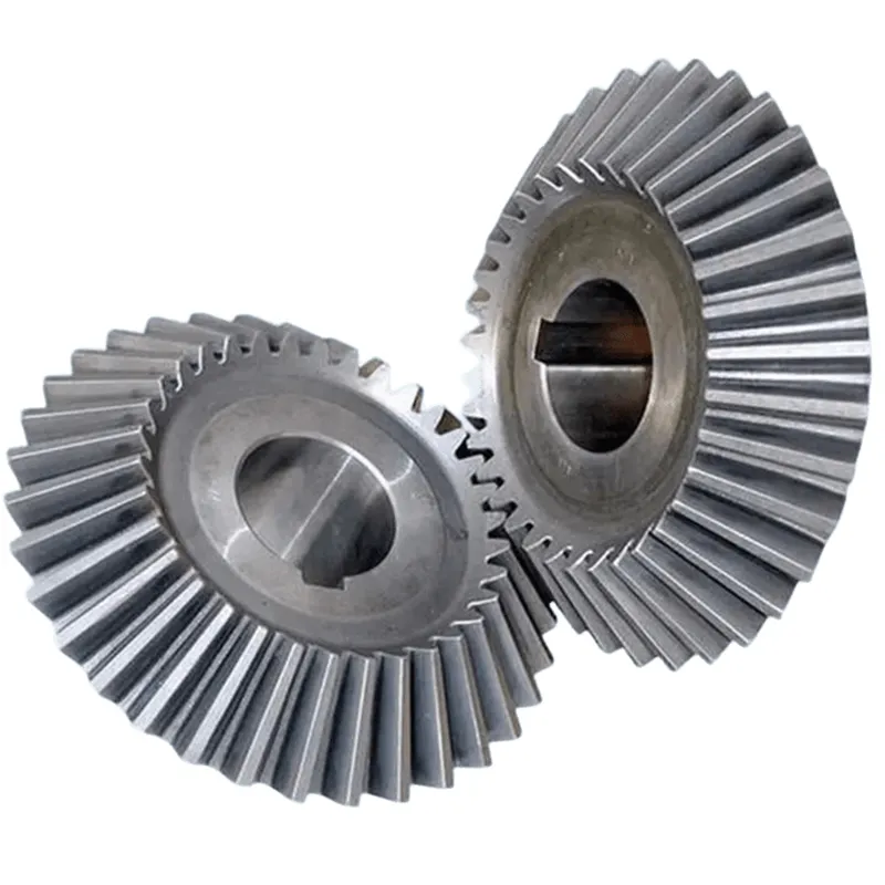
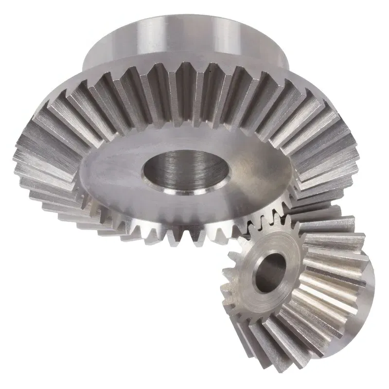
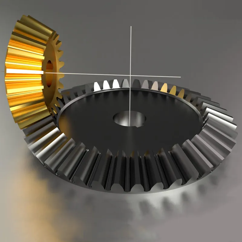
A. Straight Bevel Gears
Straight bevel gears feature teeth that are straight and conical. When measuring ingranaggi conici a denti dritti, pay close attention to the following parameters:
- Pitch diameter: Measure the pitch diameter at the back cone distance. This is where the gear meshes with its mating pinion. Use a vernier caliper or micrometer for accurate measurements.
- Tooth thickness: Check the tooth thickness at the normal section. This is measured at the standard pitch circle. A gear tooth vernier is the preferred tool for this measurement.
- Back cone distance: This is the distance from the cone center to the back face of the gear. It’s a critical dimension that affects gear alignment. Measure it using a depth micrometer or a coordinate measuring machine (CMM).
- Face angle: The angle formed by the pitch cone with the back face of the gear is the face angle. This can be measured with a bevel protractor or on a CMM. Verify that it matches the specified design angle.
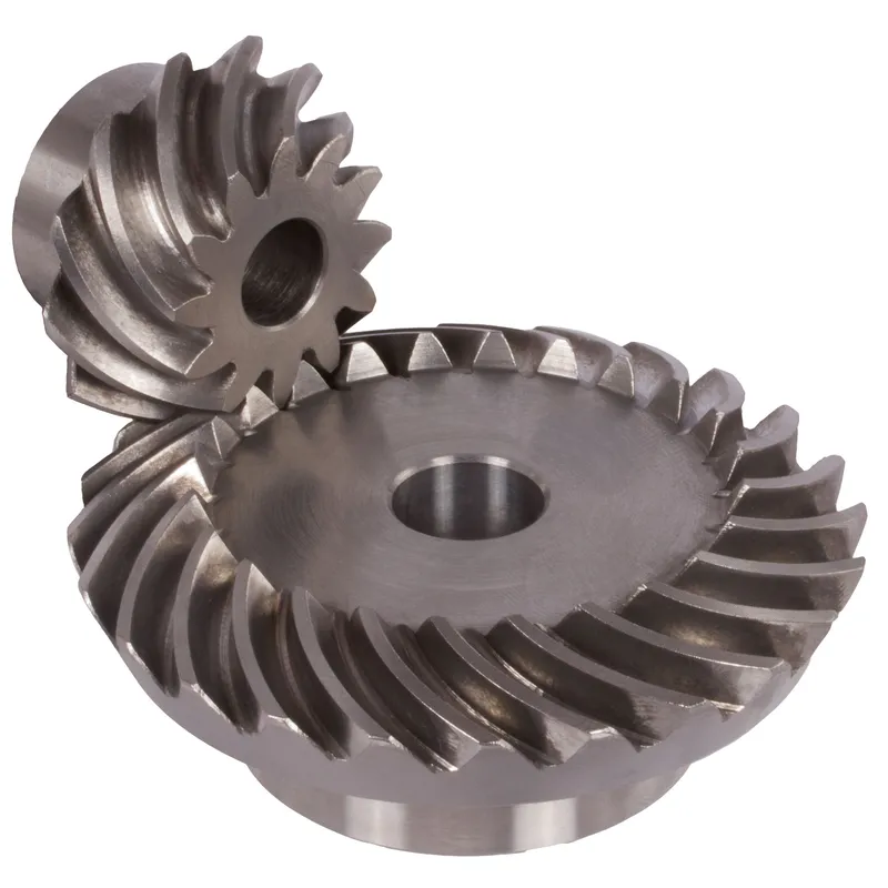
B. Spiral Bevel Gears
Spiral bevel gears have curved teeth that are positioned along diagonal lines across the surface of the cone. Key dimensions to check for spiral bevel gears include:
- Mean spiral angle: This is the angle between the tooth trace and an element of the pitch cone that passes through the middle of the tooth trace. It’s measured at the mean cone distance. Use a spiral bevel gear testing machine equipped with a dividing head for reliable measurements.
- Pressure angle: The pressure angle in a spiral bevel gear is measured at the mean point. It’s defined as the angle between a line normal to the tooth surface and a plane tangent to the pitch surface. Special tooling on a gear measuring machine is needed to accurately assess pressure angle.
- Pitch apex to crown: This is the distance in the axial plane between the pitch apex and the crown gear. The crown gear is the larger of the two mating spiral bevel gears. A direct measurement can be made using a depth micrometer.
C. Hypoid and Zerol Bevel Gears
Hypoid and Zerol bevel gears are special types of spiral bevel gears. Hypoid gears have an offset between the axes of the pinion and gear, while Zerol gears have zero offset. When measuring these gear types, focus on:
- Pitch apex to crown: Similar to spiral bevel gears, this dimension is critical for proper assembly and operation. Use a depth gauge to measure the distance from the heel end of the tooth to the pitch apex.
- Offset: For hypoid gears, the pinion axis is offset above or below the gear axis. This offset affects tooth contact and must be carefully controlled. It can be measured with a hypoid gear testing machine that simulates the operating positions of the gear and pinion.
- Spiral angle: Both hypoid and Zerol gears have spirally curved teeth. The spiral angle is defined at the mean point for these gear types. As with spiral bevel gears, use a spiral bevel gear tester with a dividing head to measure this parameter.