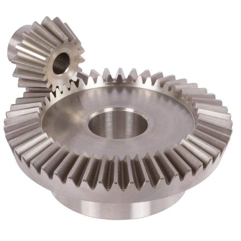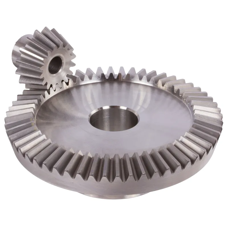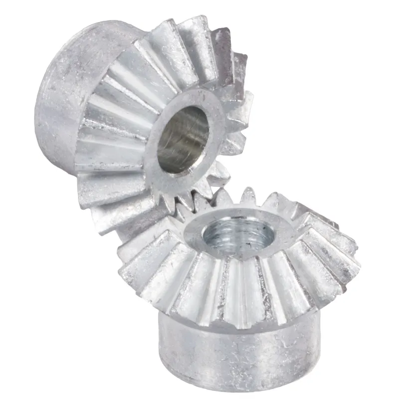
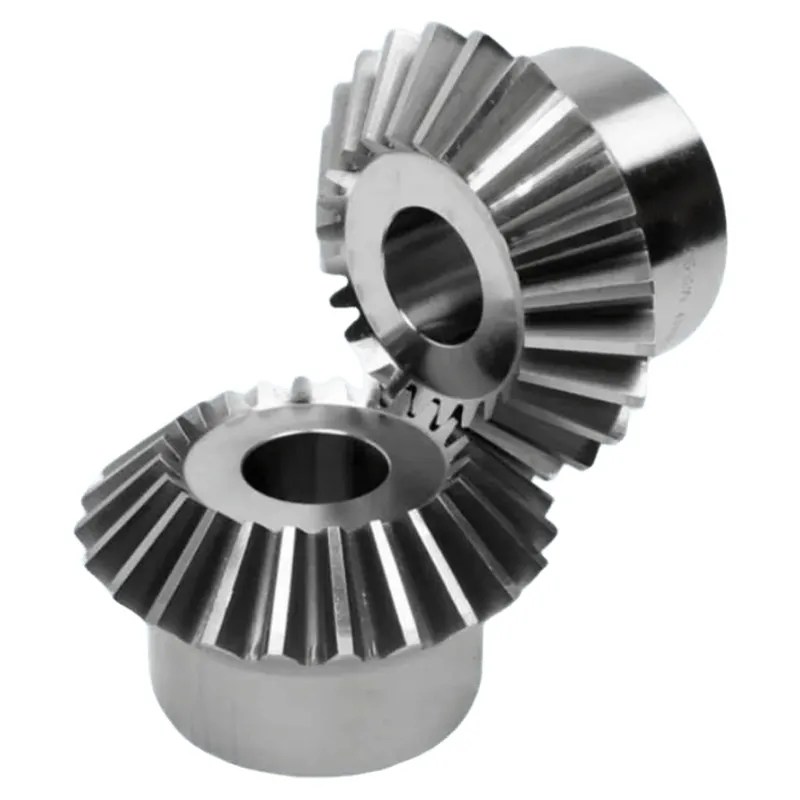
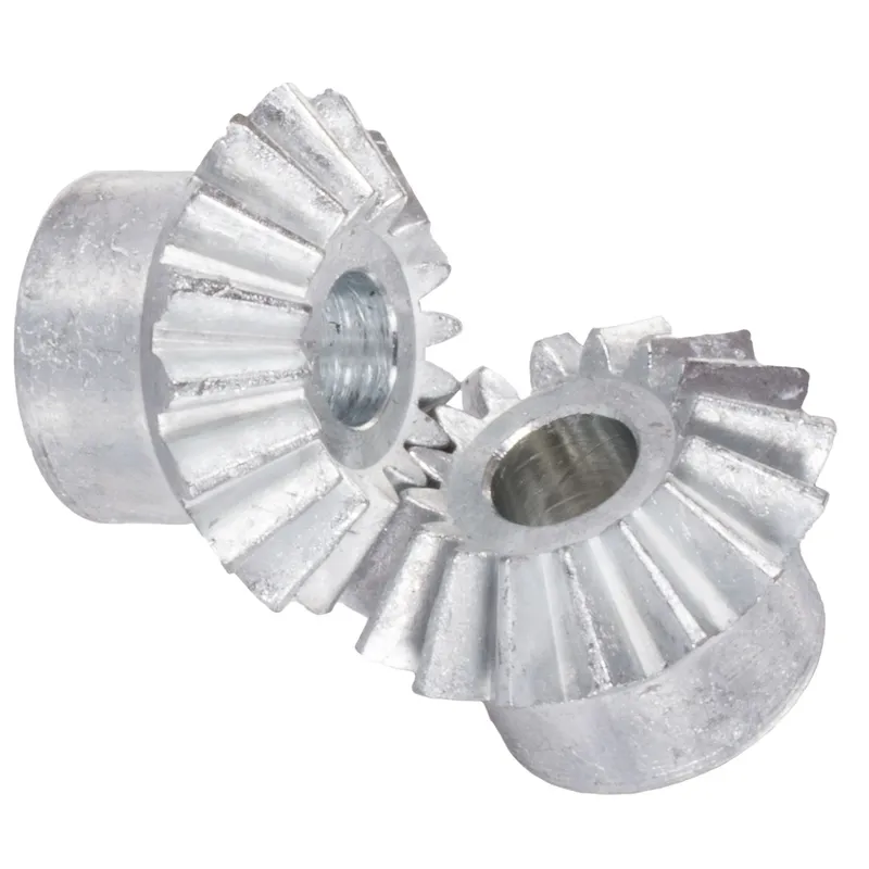
เฟืองดอกจอกหล่อขึ้นรูปจากสังกะสี อัตราทด 1:1 ระบบฟันตรง
Zinc die-cast bevel gears with a 1:1 ratio and straight-tooth system are mechanical components used to transmit torque between intersecting shafts at a 90-degree angle. The straight-tooth design features linear teeth, providing simplicity and efficiency in low-speed, low-load applications. These bevel gears are often used in machinery requiring precise motion transfer, like small-scale automation or instrumentation.
Zinc die-cast bevel gears with a 1:1 ratio and straight-tooth system are mechanical components used to transmit torque between intersecting shafts at a 90-degree angle. Made from zinc alloy (typically ZnAl4Cu1), these gears offer a cost-effective, lightweight alternative to steel or iron gears, with good strength but limited suitability for continuous operation due to material properties. The 1:1 ratio means both gears have the same number of teeth, ensuring equal rotational speed without torque multiplication. The straight-tooth design features linear teeth, providing simplicity and efficiency in low-speed, low-load applications. These gears are often used in machinery requiring precise motion transfer, like small-scale automation or instrumentation.
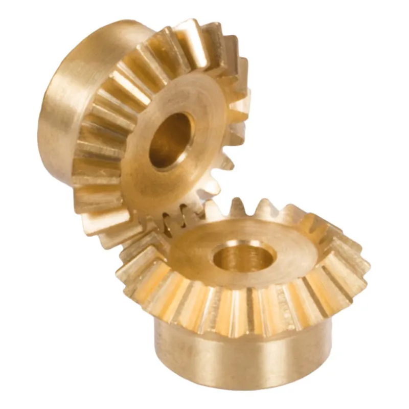
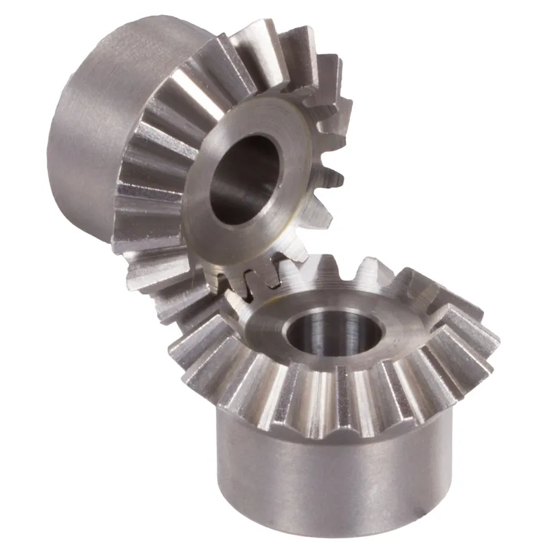
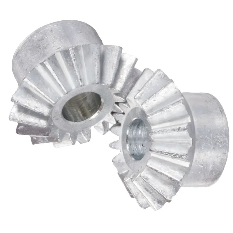
Zinc Die-Cast Bevel Gear Ratio 1:1
| 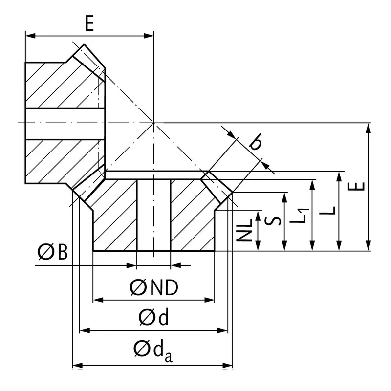 |
| โมดูล | ตัวเลข ของฟัน | งเอ | ง | เอ็นดี | เอ็นแอล | แอล1 | แอล | เอส | ข | บีH9 | อี | แรงบิด* | น้ำหนัก |
| มม. | มม. | มม. | มม. | มม. | มม. | มม. | มม. | มม. | มม. | เอ็นซีเอ็ม | จี | ||
| 1 | 16 | 17,5 | 16 | 12 | 7,5 | 13,0 | 13,0 | 10,5 | 4,5 | 6 | 17,9 | 14 | 7 |
| 1,5 | 16 | 26,0 | 24 | 19 | 10,7 | 17,0 | 18,6 | 14,5 | 6,9 | 8 | 25,5 | 46 | 27 |
| 2 | 16 | 34,6 | 32 | 23 | 10 | 19,2 | 21,3 | 15,1 | 9,6 | 10 | 30,0 | 110 | 52 |
| 2,5 | 16 | 43,3 | 40 | 26 | 12 | 23,0 | 25,5 | 17,6 | 12,3 | 12 | 36,2 | 230 | 88 |
| 3 | 16 | 52,3 | 48 | 30 | 13 | 26,0 | 29,3 | 20,6 | 14,0 | 14 | 42,5 | 380 | 146 |
| 3,5 | 16 | 61,4 | 56 | 34 | 14 | 29,2 | 33,2 | 23,2 | 15,5 | 16 | 49,4 | 580 | 228 |
- In the torque calculation of zinc-die-cast bevel gears only the root strength was considered.
- Due to the material properties these gears are only to a limited extend suitable for continuous operation.
Zinc Die-Cast Bevel Gear Production Process
The production of zinc die-cast bevel gears involves a precise, multi-step process optimized for creating durable, cost-effective components with straight-tooth designs and 1:1 ratios for intersecting shaft applications.
- Alloy Preparation: The process begins with selecting a zinc alloy, typically ZnAl4Cu1 (Zamak 5), known for its strength, ductility, and castability. Raw zinc is melted in a furnace at approximately 420–450°C, ensuring a homogeneous molten alloy. Impurities are skimmed, and the alloy is tested for composition to meet mechanical requirements.
- Mold Design and Fabrication: High-precision steel molds, or dies, are crafted to form the gear’s geometry, including straight teeth and bevel angles. These molds are designed using CAD software to ensure accurate tooth profiles and 90-degree shaft alignment. The dies are polished and coated to enhance durability and facilitate part release.
- Die-Casting Process: The molten zinc alloy is injected into the mold under high pressure (up to 20,000 psi) using a die-casting machine. This ensures the alloy fills intricate tooth details. The process is rapid, with cycle times of 10–30 seconds, allowing high production rates. Cooling occurs within the mold, solidifying the gear in seconds.
- Ejection and Trimming: Once solidified, the gear is ejected from the mold. Excess material, or flash, is removed via automated trimming or vibratory deburring to achieve precise dimensions.
- Post-Processing: Gears undergo surface treatments like polishing or plating (e.g., nickel or zinc coating) to enhance corrosion resistance. Teeth may be machined for tighter tolerances, though zinc’s castability often minimizes this need.
- Quality Control: Each gear is inspected for dimensional accuracy, tooth profile fidelity, and surface defects using tools like CMM (Coordinate Measuring Machines) and hardness testers. Gears are tested for torque capacity, ensuring suitability for low-load, low-speed applications up to 100°C.
Zinc Die-Cast Bevel Gear Purpose
- อุตสาหกรรมยานยนต์
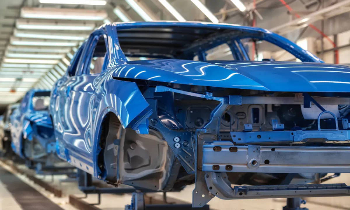
Zinc die-cast bevel gears are widely used in automotive applications such as transmission systems, steering mechanisms, and differential drives. Their lightweight design, corrosion resistance, and high strength make them suitable for enduring continuous mechanical stress and environmental exposure. - เครื่องจักรกลอุตสาหกรรม
In industrial machines, these gears are crucial components for power transmission in conveyor belts, mixers, and pumps. Their precise 1:1 ratio and durability ensure efficient motion transfer, even under heavy loads, while maintaining operational reliability. - Home Appliances
Zinc die-cast bevel gears are commonly used in home appliances like blenders, washing machines, and vacuum cleaners. Their smooth operation and resistance to wear allow for quiet, long-lasting functionality in devices subjected to regular and intensive use. - หุ่นยนต์และระบบอัตโนมัติ
These gears play a vital role in robotics and automated systems, where precise motion control is essential. Their ability to transmit power at right angles, combined with their compact size and durability, ensures efficient performance in complex robotic movements. - การบินและอวกาศและการป้องกันประเทศ
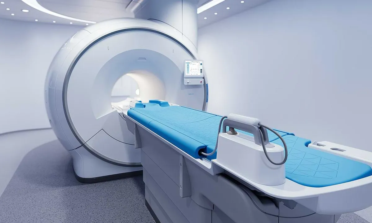
In aerospace and defense applications, zinc die-cast bevel gears are used in control systems and navigation mechanisms. Their lightweight nature and ability to withstand harsh environments make them ideal for maintaining functionality in extreme conditions. - Medical Equipment
Medical devices, such as imaging machines and surgical robots, rely on zinc die-cast bevel gears for precision and reliability. Their corrosion resistance and consistent performance under sterilization processes ensure they meet the stringent standards of medical applications.
 |  |
| เฟืองดอกจอกสำหรับอุตสาหกรรมยานยนต์ | Bevel Gear for Robotics Industry |
 |  |
| เฟืองดอกจอกสำหรับอุตสาหกรรมการบินและอวกาศ | เฟืองดอกจอกสำหรับอุตสาหกรรมการแพทย์ |
Bevel Gear Vs Miter Gear
เฟืองมิตเตอร์เป็นเฟืองชนิดหนึ่งที่มีฟันตัดกันเป็นมุม 90 องศา ออกแบบมาเพื่อส่งกำลังและการเคลื่อนที่ระหว่างเพลาสองตัวที่ตั้งฉากกัน เฟืองมิตเตอร์นิยมใช้ในงานเชิงกลหลากหลายประเภท รวมถึงเครื่องจักรในอุตสาหกรรม ระบบยานยนต์ และเครื่องมือวัดความแม่นยำ
The teeth of miter gears are cut at a 45-degree angle to the axis of rotation, allowing them to mesh together smoothly and efficiently. This unique tooth geometry enables miter gears to change the direction of rotation while maintaining a constant velocity ratio between the input and output shafts.
ข้อดีของเฟืองมิตเตอร์
ดีไซน์กะทัดรัด
เนื่องจากการจัดเรียงในแนวตั้งฉาก เฟืองแบบมุมฉากจึงช่วยให้ระบบส่งกำลังมีประสิทธิภาพในการใช้พื้นที่มากกว่าเมื่อเทียบกับเฟืองประเภทอื่นๆ
ประสิทธิภาพสูง
การประสานกันอย่างแม่นยำของฟันเฟืองช่วยให้การถ่ายทอดการเคลื่อนที่และแรงบิดระหว่างเพลาที่ตัดกันเป็นไปอย่างราบรื่นและมีประสิทธิภาพ ประสิทธิภาพสูงนี้ส่งผลให้การใช้พลังงานลดลงและประสิทธิภาพโดยรวมของระบบดีขึ้น
ความอเนกประสงค์
เฟืองมิตเตอร์มีความอเนกประสงค์สูงและสามารถใช้งานได้หลากหลายในอุตสาหกรรมต่างๆ เหมาะสำหรับการใช้งานทั้งความเร็วต่ำและความเร็วสูง รวมถึงการส่งกำลังที่มีน้ำหนักเบาถึงปานกลาง
ข้อเสียของเฟืองตัดเฉียง
ความสามารถในการรับน้ำหนักจำกัด
เมื่อเปรียบเทียบกับเฟืองเอียงประเภทอื่นๆ เช่น เฟืองเอียงเกลียว เฟืองเอียงมีกำลังรับน้ำหนักค่อนข้างจำกัด การสัมผัสแบบจุดระหว่างฟันเฟืองส่งผลให้เกิดความเค้นกระจุกตัวสูงขึ้น ซึ่งอาจนำไปสู่การสึกหรอเร็วและอายุการใช้งานของเฟืองลดลงภายใต้ภาระหนัก
กระแสต่อต้าน
เฟืองมุมฉากมักเกิดการคลายตัว ซึ่งหมายถึงช่องว่างระหว่างฟันเฟืองที่ประกบกัน การคลายตัวนี้อาจทำให้เกิดข้อผิดพลาดในการกำหนดตำแหน่ง การสั่นสะเทือน และเสียงดังในระบบเฟือง
ความไวในการจัดแนว
การเยื้องศูนย์ใดๆ ระหว่างเพลาที่ตัดกันอาจนำไปสู่การสึกหรอ การสั่นสะเทือนที่เพิ่มขึ้น และอายุการใช้งานของเฟืองที่ลดลง
Bevel gears are a type of mechanical gear that features conically-shaped teeth, allowing them to transmit power between intersecting shafts at various angles. Unlike miter gears, which are limited to 90-degree angles, bevel gears offer greater flexibility in shaft orientation. These gears find extensive use in a wide range of machinery and applications where power transmission between non-parallel shafts is required.
เฟืองดอกจอกมีหลายรูปแบบ ได้แก่ เฟืองดอกจอกตรง เฟืองดอกจอกเกลียว และเฟืองดอกจอกไฮปอยด์
- Straight bevel gears have teeth that are cut straight across the cone surface, while spiral bevel gears feature curved teeth for smoother and quieter operation.
- เฟืองดอกจอกไฮปอยด์ ซึ่งเป็นรูปแบบหนึ่งของเฟืองดอกจอกเกลียว มีแกนเฟืองตัวเล็กที่เยื้องศูนย์ เพื่อเพิ่มความสามารถในการรับแรงบิดและลดเสียงรบกวน
ข้อดีของเฟืองดอกจอก
มุมเพลาอเนกประสงค์
ข้อดีหลักประการหนึ่งของเฟืองดอกจอกคือความสามารถในการส่งกำลังระหว่างเพลาที่ทำมุมต่างๆ ได้ ไม่จำกัดเฉพาะ 90 องศาเหมือนเฟืองเฉียง
การทำงานราบรื่นและเงียบ
เฟืองดอกจอกเกลียวและเฟืองดอกจอกไฮปอยด์ให้การทำงานที่ราบรื่นและเงียบกว่าเมื่อเทียบกับเฟืองดอกจอกแบบตรง ฟันโค้งของเฟืองดอกจอกเกลียวช่วยให้การเข้าเกียร์ค่อยเป็นค่อยไปมากขึ้น ลดการสั่นสะเทือนและเสียงรบกวน
ความสามารถในการรับแรงบิดสูง
Bevel gears, particularly hypoid bevel gears, are capable of transmitting high torque loads. The offset pinion axis in hypoid gears allows for larger tooth contact areas, increasing their load-carrying capacity.
ดีไซน์กะทัดรัด
เฟืองดอกจอกช่วยให้สามารถออกแบบที่กะทัดรัดได้ โดยการส่งกำลังระหว่างเพลาที่ตัดกันในพื้นที่ที่เล็กกว่าเมื่อเทียบกับการจัดเรียงเฟืองแบบอื่นๆ
ข้อเสียของเฟืองดอกจอก
การผลิตที่ซับซ้อน
กระบวนการผลิตเฟืองดอกจอก โดยเฉพาะเฟืองดอกจอกเกลียวและเฟืองดอกจอกไฮปอยด์ มีความซับซ้อนและต้นทุนสูงกว่าเฟืองประเภทอื่นๆ
แรงเสียดทานและการเกิดความร้อนที่สูงขึ้น
เนื่องจากการเลื่อนไปมาระหว่างฟันเฟือง ทำให้เฟืองเอียงมีแรงเสียดทานสูงกว่าเฟืองตรงหรือเฟืองเกลียว
มีโอกาสเกิดกระแสต่อต้าน
เฟืองดอกจอกอาจเกิดการคลายตัว ซึ่งเป็นช่องว่างหรือระยะคลอนระหว่างฟันเฟืองที่ประกบกัน การคลายตัวนี้อาจส่งผลให้ความแม่นยำในการกำหนดตำแหน่งลดลงและสึกหรอมากขึ้น โดยเฉพาะอย่างยิ่งในงานที่ต้องการการกำหนดตำแหน่งที่แม่นยำหรือการทำงานที่ความเร็วต่ำ
อัตราส่วนความเร็วที่จำกัด
แม้ว่าเฟืองดอกจอกจะให้ความยืดหยุ่นในเรื่องมุมของเพลา แต่ก็มีข้อจำกัดในเรื่องอัตราส่วนความเร็วที่ทำได้ เมื่อเทียบกับเฟืองประเภทอื่น เช่น เฟืองตัวหนอน

ความแตกต่างที่สำคัญระหว่างเฟืองเฉียงและเฟืองดอกจอก
แม้ว่าทั้งเฟืองเฉียงและเฟืองดอกจอกจะถูกใช้ในการส่งกำลังระหว่างเพลาที่ตัดกัน แต่ก็มีความแตกต่างที่ชัดเจนในด้านการออกแบบ ฟังก์ชันการทำงาน และข้อได้เปรียบเชิงกล
ออกแบบ
เฟืองมิตเตอร์เป็นเฟืองดอกจอกชนิดหนึ่งที่ออกแบบมาเพื่อใช้งานกับเพลาที่ทำมุม 90 องศา
ในทางตรงกันข้าม เฟืองดอกจอกสามารถออกแบบให้ใช้งานได้กับมุมใดๆ ก็ได้ระหว่าง 0 ถึง 180 องศา ทำให้มีความยืดหยุ่นมากขึ้นในการจัดตำแหน่งเพลา
การทำงาน
เฟืองเฉียงมักใช้ในงานที่ต้องการเปลี่ยนทิศทางการเคลื่อนที่หรือการส่งกำลัง 90 องศา โดยทั่วไปจะพบได้ในเครื่องมือช่าง อุปกรณ์เฟืองท้ายรถยนต์ และเครื่องจักรในอุตสาหกรรม
ในทางกลับกัน เฟืองดอกจอกมีความยืดหยุ่นมากกว่าในแง่ของมุมเพลา และถูกนำไปใช้ในงานที่หลากหลายกว่า เช่น ระบบขับเคลื่อนในรถยนต์ ระบบควบคุมในเครื่องบิน และการส่งกำลังในเครื่องจักรต่างๆ
ความได้เปรียบเชิงกล
โดยทั่วไปแล้วเฟืองแบบมิตเตอร์จะมีอัตราทดเกียร์ 1:1 ซึ่งหมายความว่ามันไม่ได้ให้ข้อได้เปรียบเชิงกลใดๆ ในแง่ของความเร็วหรือแรงบิด
อย่างไรก็ตาม เฟืองดอกจอกสามารถออกแบบให้มีอัตราทดเกียร์ที่แตกต่างกันได้ ทำให้สามารถลดความเร็วหรือเพิ่มแรงบิดได้ ขึ้นอยู่กับข้อกำหนดของงาน
ข้อกำหนดด้านน้ำหนักบรรทุก
ความสามารถในการรับน้ำหนักของเฟืองเฉียงและเฟืองดอกจอกแตกต่างกันไปตามปัจจัยต่างๆ เช่น วัสดุ ความแข็งของพื้นผิว และรูปทรงของฟัน โดยทั่วไปแล้ว เฟืองดอกจอกสามารถรับน้ำหนักได้มากกว่าเฟืองเฉียง เนื่องจากสามารถกระจายแรงเค้นได้สม่ำเสมอกว่าตามพื้นผิวของฟัน
ข้อจำกัดด้านพื้นที่
เฟืองเฉียงมีขนาดกะทัดรัดกว่าและใช้พื้นที่ในการติดตั้งน้อยกว่า ทำให้เหมาะสำหรับงานที่มีพื้นที่จำกัด ในขณะที่เฟืองดอกจอก แม้ว่าจะใช้งานได้หลากหลายกว่าในแง่ของมุมเพลา แต่ก็อาจต้องการพื้นที่มากกว่าเพื่อรองรับขนาดที่ใหญ่กว่าและการวางตำแหน่งเชิงมุม
ข้อมูลเพิ่มเติม
| เรียบเรียงโดย | วายเจเอ็กซ์ |
|---|