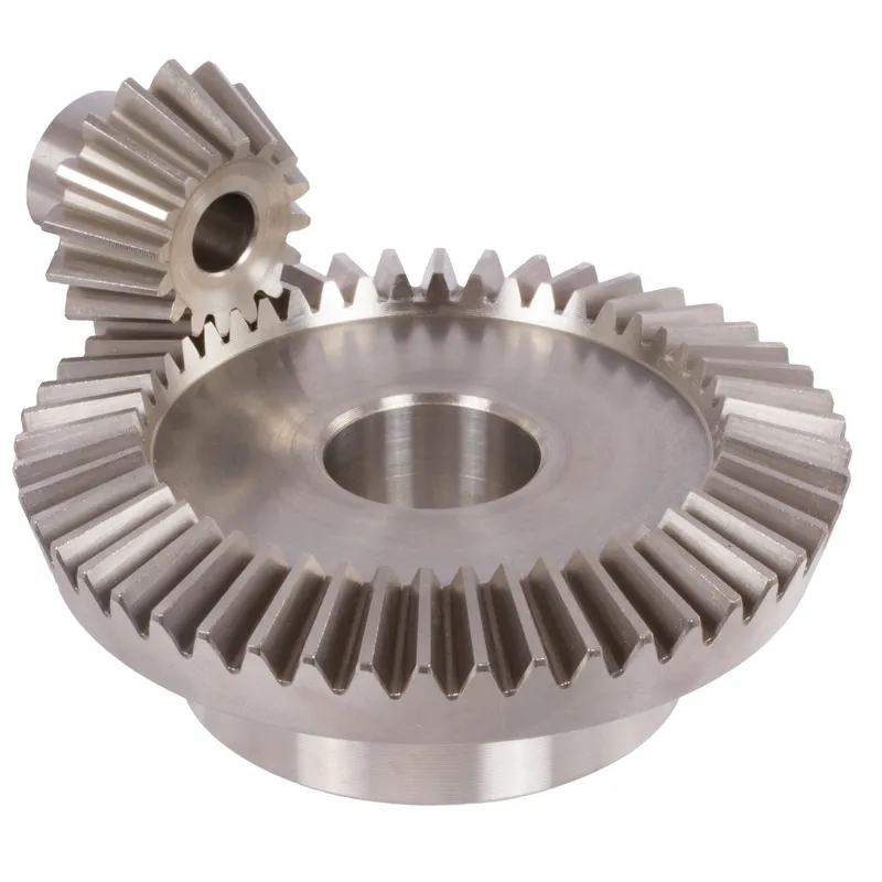
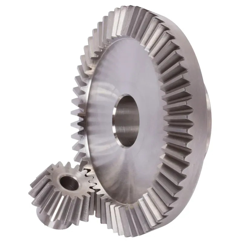
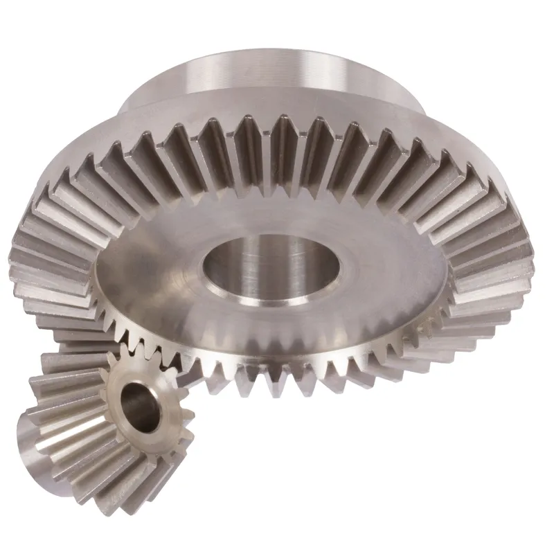
Конические шестерни из нержавеющей стали, передаточное число 4:1, система прямых зубьев.
The stainless steel bevel gears ratio 4:1 straight-tooth system is a mechanical gear setup designed for efficient power transmission between two intersecting shafts, typically at a right angle (90°). These bevel gears are made of durable stainless steel, offering excellent resistance to corrosion, wear, and high-temperature environments, making them suitable for demanding industrial applications.
The stainless steel bevel gears ratio 4:1 straight-tooth system is a mechanical gear setup designed for efficient power transmission between two intersecting shafts, typically at a right angle (90°). These bevel gears are made of durable stainless steel, offering excellent resistance to corrosion, wear, and high-temperature environments, making them suitable for demanding industrial applications.
The term 4:1 ratio indicates that the smaller gear (pinion) completes four revolutions for every one revolution of the larger gear. This allows for a significant reduction in speed while amplifying torque. The straight-tooth design refers to the linear, radially arranged gear teeth, which are simpler to manufacture and align compared to spiral bevel gears. While slightly noisier due to abrupt tooth engagement, they are ideal for low to moderate-speed applications where precision and durability are essential.
Stainless Steel Bevel Gear Ratio 4:1
| 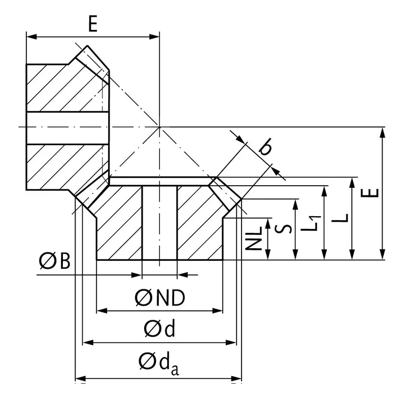 |
| Модуль | Число зубов | да | д | НД | Нидерланды | Л1 | Л | С | б | БН7 | Э | Крутящий момент* | Масса |
| мм | мм | мм | мм | мм | мм | мм | мм | мм | мм | Нсм | г | ||
| 1 | 15 | 17,8 | 15 | 13 | 7,7 | 17,3 | 17,3 | 8,4 | 9,3 | 5 | 38 | 0,14 | 15 |
| 1 | 60 | 60,3 | 60 | 30 | 10,0 | 15 | 17,1 | 15,1 | 9,3 | 8 | 22 | 0,56 | 160 |
| 1,5 | 15 | 26,7 | 22,5 | 18 | 14,45 | 28 | 28,9 | 15,5 | 13,9 | 8 | 60 | 0,48 | 42 |
| 1,5 | 60 | 90,4 | 90 | 50 | 12,0 | 25 | 27,6 | 24,6 | 13,9 | 15 | 35 | 1,92 | 745 |
| 2 | 15 | 34,0 | 30 | 20 | 13,5 | 29 | 29,9 | 15,5 | 15 | 10 | 75 | 1,34 | 80 |
| 2 | 60 | 120,9 | 120 | 60 | 20,0 | 35 | 40,1 | 37,0 | 15 | 25 | 50 | 5,36 | 1600 |
| 2,5 | 15 | 42,5 | 37,5 | 30 | 16,1 | 35 | 36,8 | 17,6 | 20 | 10 | 92 | 2,5 | 190 |
| 2,5 | 60 | 151,2 | 150 | 80 | 18,0 | 33 | 37,8 | 33,8 | 20 | 25 | 50 | 10,0 | 2600 |
| 3 | 15 | 51,0 | 45 | 30 | 13,15 | 38 | 39,7 | 15,7 | 25 | 10 | 105 | 4,4 | 270 |
| 3 | 60 | 181,5 | 180 | 80 | 18,0 | 35 | 40,6 | 35,5 | 25 | 30 | 55 | 17,6 | 3800 |
| 4 | 15 | 68,0 | 60 | 40 | 12,5 | 43 | 44,8 | 16,0 | 30 | 20 | 135 | 8,9 | 520 |
| 4 | 60 | 242,0 | 240 | 90 | 20,0 | 41 | 50,1 | 44,0 | 30 | 30 | 70 | 35,6 | 8300 |
Advantages of Stainless Steel Bevel Gears
Высокий крутящий момент
One of the key advantages of stainless steel bevel gears is their ability to handle high torque loads. The geometry and design of bevel gears allow for efficient transmission of power and torque between intersecting shafts.
Компактный дизайн
Конические зубчатые передачи представляют собой компактное решение для передачи мощности между непараллельными валами. Благодаря конической геометрии, конические зубчатые передачи позволяют эффективно изменять направление вращения в ограниченном пространстве.
Плавная и тихая работа
При правильном проектировании и изготовлении конические зубчатые передачи обеспечивают плавную и бесшумную работу. Усовершенствования в геометрии зубьев, такие как использование спиральных конических передач и гипоидных передач, значительно улучшили плавность хода и шумоподавление конических передач. Изогнутый профиль зубьев спиральных конических передач обеспечивает плавное зацепление и расцепление, что приводит к более тихой работе по сравнению с прямыми коническими передачами.
Универсальность в углах наклона вала
Конические зубчатые передачи обеспечивают гибкость в плане углов наклона валов. Хотя наиболее распространенный угол наклона вала для конических зубчатых передач составляет 90 градусов, их можно спроектировать для работы с различными углами наклона валов.
Disadvantages of Stainless Steel Bevel Gears
Повышенная сложность производства
One of the main disadvantages of stainless steel bevel gears is their higher manufacturing complexity compared to other gear types, such as spur gears. The production of bevel gears requires specialized machinery and precise manufacturing processes to achieve the desired tooth geometry and surface finish. This complexity can result in increased manufacturing costs and longer lead times.
Чувствительность к смещению
Конические зубчатые передачи более чувствительны к несоосности по сравнению с другими типами передач. Несоосность может привести к неравномерному распределению нагрузки, увеличению напряжения на зубьях и преждевременному выходу из строя.
Ограниченные возможности скорости
Конические зубчатые передачи имеют ограничения по скорости вращения. На высоких скоростях конические зубчатые передачи склонны к возникновению чрезмерного шума и вибрации из-за скольжения между зубьями. Это может привести к снижению эффективности и увеличению износа. В результате конические зубчатые передачи обычно используются в областях применения с умеренными или низкими требованиями к скорости вращения.
Более высокая стоимость
Сложность и точность изготовления конических зубчатых передач часто приводят к более высоким затратам по сравнению с более простыми типами передач. Необходимость в специализированном оборудовании, квалифицированной рабочей силе и строгих мерах контроля качества способствует увеличению стоимости конических зубчатых передач. Кроме того, индивидуальные требования к конструкции и специфика конических зубчатых передач для конкретных областей применения могут еще больше повысить их стоимость.
What Are Bevel Gears Used For
Передача энергии в автомобилях
Bevel gears find extensive use in the automotive industry, particularly in differential drives. In a differential, straight bevel gears are used to split the power from the driveshaft and transmit it to the wheels while allowing them to rotate at different speeds. This enables smooth cornering and improved traction control. Bevel gears are also used in various other automotive applications, such as transfer cases and steering systems.
Промышленное оборудование
Конические зубчатые передачи широко используются в промышленном оборудовании, где необходимо передавать мощность между пересекающимися валами. Они применяются в самых разных устройствах, включая редукторы, понижающие передачи и системы передачи мощности. К промышленным применениям конических зубчатых передач относятся горнодобывающая техника, строительная техника, печатные станки и текстильное оборудование.
Аэрокосмическая и авиационная промышленность
The aerospace and aviation industries rely on stainless steel bevel gears for power transmission in various applications. Bevel gears are used in aircraft engines, rotor drive systems, and accessory gearboxes. They are designed to handle high loads and provide reliable performance in demanding operating conditions. The compact design and ability to transmit power between non-parallel shafts make bevel gears well-suited for aerospace applications where space is limited.
Применение в морской отрасли
Конические зубчатые передачи используются в морских системах для передачи мощности в силовых установках, системах рулевого управления и палубном оборудовании. Они применяются в морских редукторах, подруливающих устройствах и лебедках. Способность конических зубчатых передач выдерживать высокие крутящие моменты и суровые условия морской среды делает их подходящими для этих применений. Морские конические зубчатые передачи часто изготавливаются из коррозионностойких материалов для обеспечения долговечности и надежности.
 |  |
| Конические шестерни для автомобильных дифференциалов | Коническая зубчатая передача для промышленного оборудования |
 |  |
| Конические шестерни для робототехники | Конические зубчатые передачи для морской промышленности |
Stainless Steel Bevel Gear Measurement
Step 1: Gather Required Tools and Equipment
To accurately measure bevel gears, you will need the following tools:
- Vernier caliper or micrometer for measuring tooth thickness, depth, and pitch diameter
- Bevel protractor for measuring pitch and root angles
- Gear tooth vernier caliper for measuring tooth thickness at a specific depth
- Surface plate and height gauge for checking gear runout and mounting distance
Step 2: Measure Pitch Diameter
To measure pitch diameter:
- Place the bevel gear on a surface plate with the back face down.
- Position the height gauge perpendicular to the surface plate and align its measuring tip with the pitch line on a gear tooth flank.
- Zero the height gauge at this position.
- Rotate the gear 180 degrees and measure the height at the corresponding pitch line on the opposite tooth flank.
- The pitch diameter is calculated by adding the two height measurements.
Repeat this process on multiple teeth around the gear to ensure consistency and check for potential runout issues.
Step 3: Measure Tooth Thickness
To measure tooth thickness:
- Use a gear tooth vernier caliper positioned at the pitch line.
- Measure the thickness of a tooth at the pitch line, taking care not to damage the tooth profile.
- Repeat this measurement on several teeth around the gear, noting any variations.
Alternatively, a standard vernier caliper or micrometer can be used to measure the chordal thickness at the base of the tooth.
Step 4: Measure Pressure and Root Angles
To measure these angles:
- Place the bevel protractor on the pitch cone of the gear, aligning its edge with a tooth flank.
- Read the pressure angle directly from the protractor scale at the point of tangency with the tooth profile.
- Reposition the protractor to align with the root line of the tooth to measure the root angle.
Verify that the measured angles match the specified gear design parameters.
Step 5: Inspect Gear Runout
Gear runout refers to the variation in gear geometry as it rotates about its axis. To check runout:
- Mount the bevel gear on a mandrel or arbor supported by V-blocks on a surface plate.
- Position a dial indicator with its probe contacting the back face of the gear near the outer diameter.
- Slowly rotate the gear, noting the total indicator reading (TIR) on the dial.
- Compare the measured TIR to the specified tolerance for runout.
Repeat this process at the front face of the gear and at the pitch diameter to fully evaluate gear runout.
Step 6: Verify Mounting Distance
The mounting distance is the axial position of the bevel gear relative to its mating gear. To verify mounting distance:
- Place the bevel gear on a surface plate with its front face down.
- Use a height gauge to measure the distance from the surface plate to the back face of the gear at the specified mounting distance radius.
- Compare this measurement to the gear’s designed mounting distance.
Детали
| Отредактировано | Yjx |
|---|
Похожие товары
-
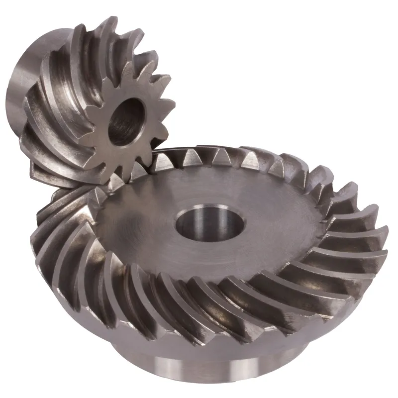
Стальные спирально-конические шестерни с передаточным отношением 1:1 – 4:1. Система спиральных зубьев.
-
Стальные спирально-конические шестерни с передаточным числом 3:1. Система спиральных зубьев.
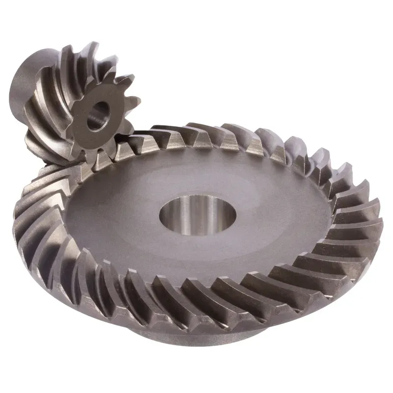
-

Стальные спирально-зубчатые конические шестерни с передаточным отношением 1,214:1. Система спиральных зубьев.
-
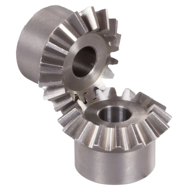
Стальные конические зубчатые передачи с передаточным отношением 1:1 и прямыми зубьями.
-
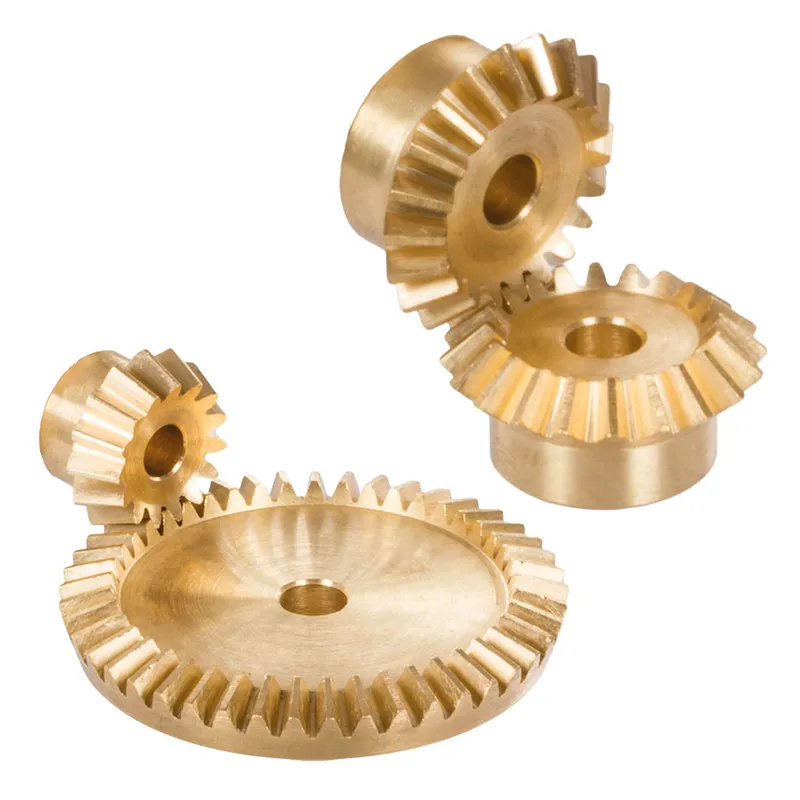
Латунные конические шестерни с передаточным отношением 1:1 – 4:1, система с прямыми зубьями


