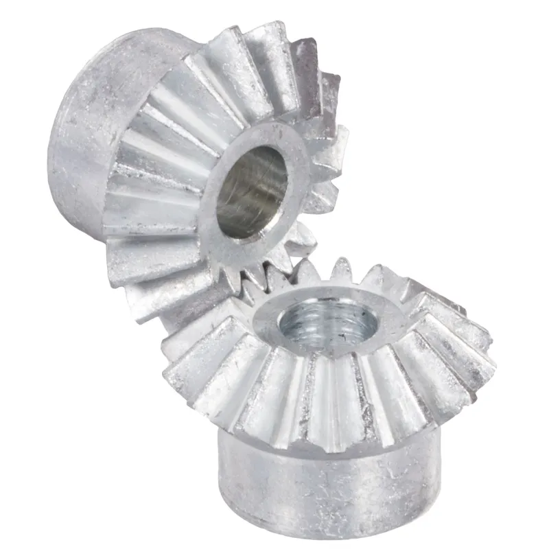
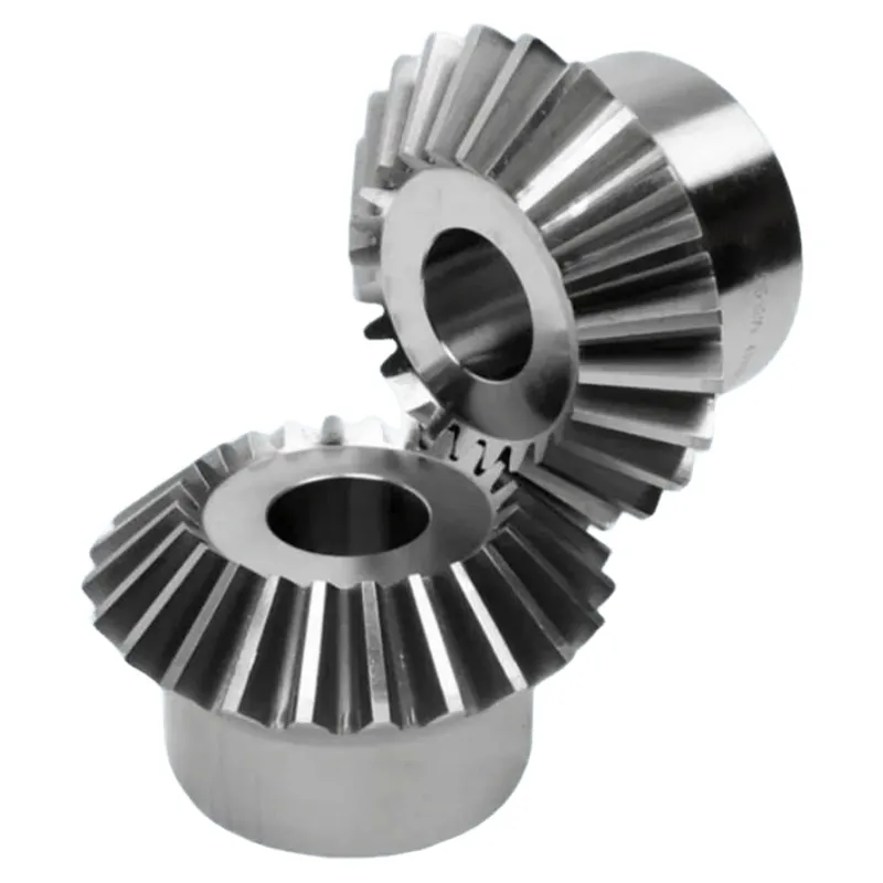
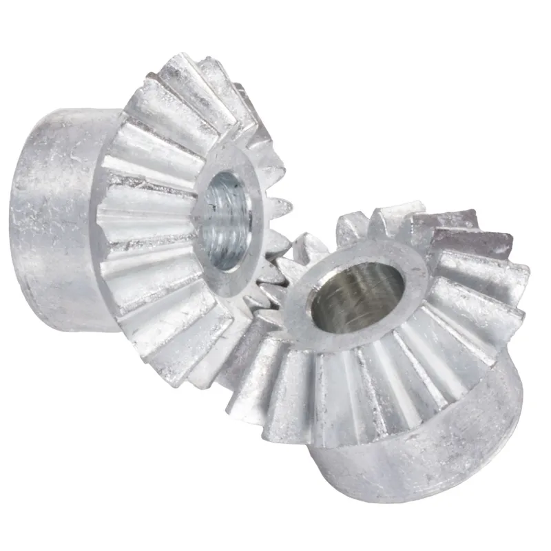
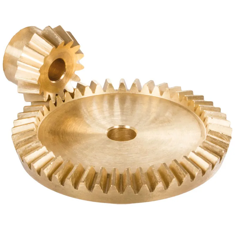
Zinc Die-Cast Bevel Gears Ratio 1:1 Straight-Tooth System
Zinc die-cast bevel gears with a 1:1 ratio and straight-tooth system are mechanical components used to transmit torque between intersecting shafts at a 90-degree angle. The straight-tooth design features linear teeth, providing simplicity and efficiency in low-speed, low-load applications. These bevel gears are often used in machinery requiring precise motion transfer, like small-scale automation or instrumentation.
Zinc die-cast bevel gears with a 1:1 ratio and straight-tooth system are mechanical components used to transmit torque between intersecting shafts at a 90-degree angle. Made from zinc alloy (typically ZnAl4Cu1), these gears offer a cost-effective, lightweight alternative to steel or iron gears, with good strength but limited suitability for continuous operation due to material properties. The 1:1 ratio means both gears have the same number of teeth, ensuring equal rotational speed without torque multiplication. The straight-tooth design features linear teeth, providing simplicity and efficiency in low-speed, low-load applications. These gears are often used in machinery requiring precise motion transfer, like small-scale automation or instrumentation.
Zinc Die-Cast Bevel Gear Ratio 1:1
| 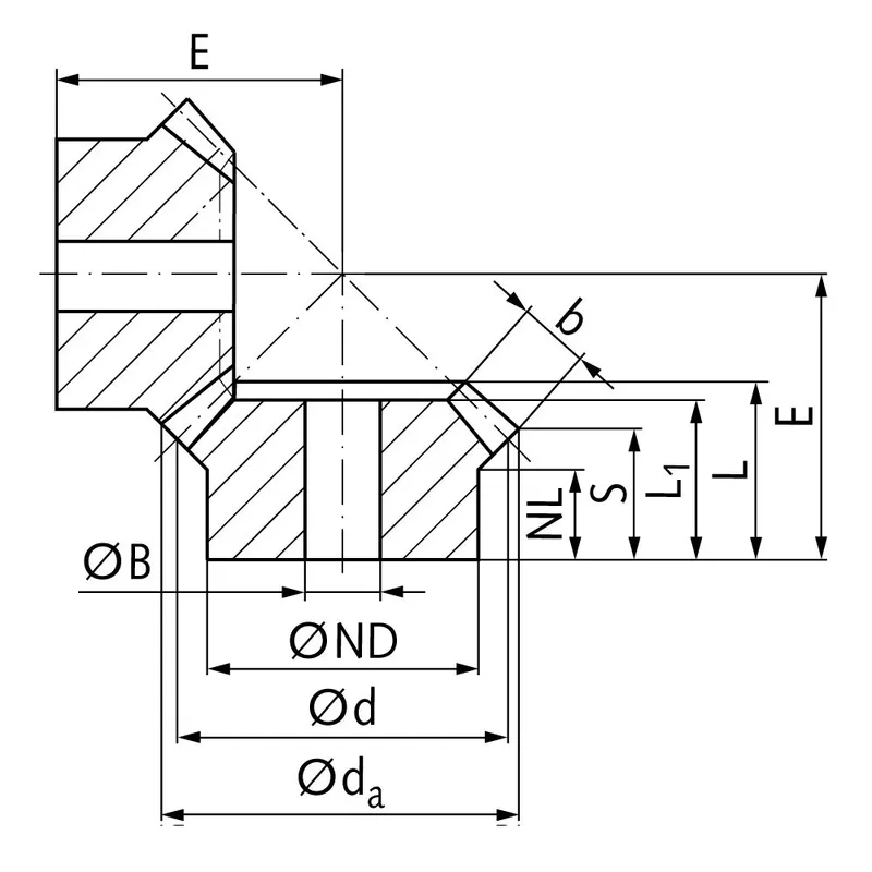 |
| Módulo | Número de dentes | dum | d | ND | Holanda | eu1 | eu | S | b | BH9 | E | Torque* | Peso |
| milímetros | milímetros | milímetros | milímetros | milímetros | milímetros | milímetros | milímetros | milímetros | milímetros | Ncm | g | ||
| 1 | 16 | 17,5 | 16 | 12 | 7,5 | 13,0 | 13,0 | 10,5 | 4,5 | 6 | 17,9 | 14 | 7 |
| 1,5 | 16 | 26,0 | 24 | 19 | 10,7 | 17,0 | 18,6 | 14,5 | 6,9 | 8 | 25,5 | 46 | 27 |
| 2 | 16 | 34,6 | 32 | 23 | 10 | 19,2 | 21,3 | 15,1 | 9,6 | 10 | 30,0 | 110 | 52 |
| 2,5 | 16 | 43,3 | 40 | 26 | 12 | 23,0 | 25,5 | 17,6 | 12,3 | 12 | 36,2 | 230 | 88 |
| 3 | 16 | 52,3 | 48 | 30 | 13 | 26,0 | 29,3 | 20,6 | 14,0 | 14 | 42,5 | 380 | 146 |
| 3,5 | 16 | 61,4 | 56 | 34 | 14 | 29,2 | 33,2 | 23,2 | 15,5 | 16 | 49,4 | 580 | 228 |
- In the torque calculation of zinc-die-cast bevel gears only the root strength was considered.
- Due to the material properties these gears are only to a limited extend suitable for continuous operation.
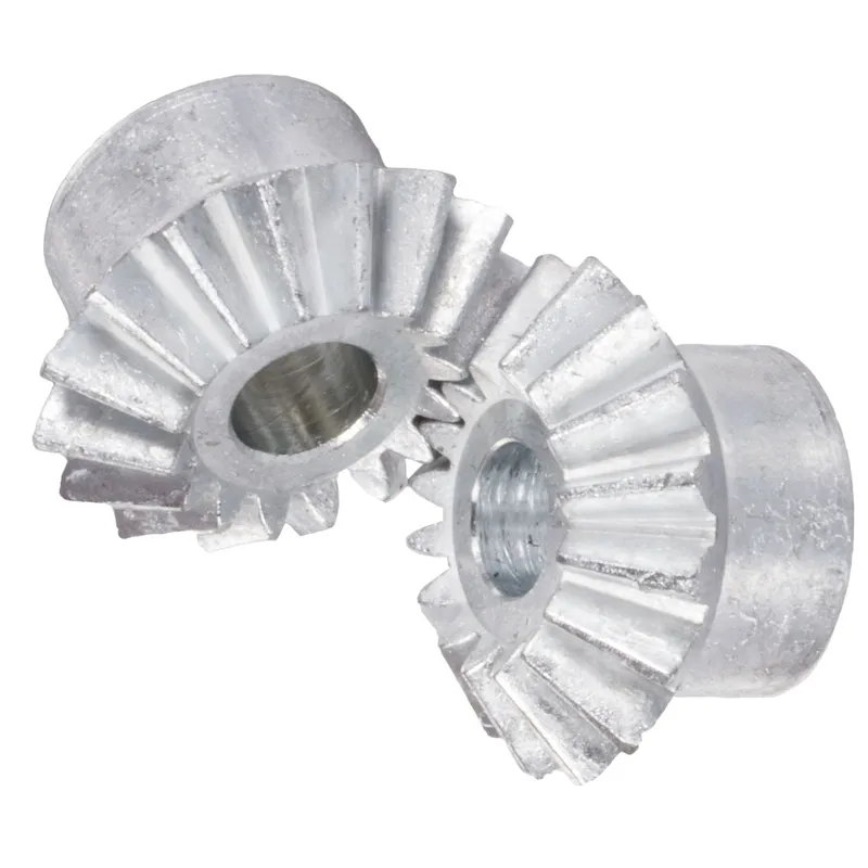
Zinc Die-Cast Bevel Gear Production Process
The production of zinc die-cast bevel gears involves a precise, multi-step process optimized for creating durable, cost-effective components with straight-tooth designs and 1:1 ratios for intersecting shaft applications.
- Alloy Preparation: The process begins with selecting a zinc alloy, typically ZnAl4Cu1 (Zamak 5), known for its strength, ductility, and castability. Raw zinc is melted in a furnace at approximately 420–450°C, ensuring a homogeneous molten alloy. Impurities are skimmed, and the alloy is tested for composition to meet mechanical requirements.
- Mold Design and Fabrication: High-precision steel molds, or dies, are crafted to form the gear’s geometry, including straight teeth and bevel angles. These molds are designed using CAD software to ensure accurate tooth profiles and 90-degree shaft alignment. The dies are polished and coated to enhance durability and facilitate part release.
- Die-Casting Process: The molten zinc alloy is injected into the mold under high pressure (up to 20,000 psi) using a die-casting machine. This ensures the alloy fills intricate tooth details. The process is rapid, with cycle times of 10–30 seconds, allowing high production rates. Cooling occurs within the mold, solidifying the gear in seconds.
- Ejection and Trimming: Once solidified, the gear is ejected from the mold. Excess material, or flash, is removed via automated trimming or vibratory deburring to achieve precise dimensions.
- Post-Processing: Gears undergo surface treatments like polishing or plating (e.g., nickel or zinc coating) to enhance corrosion resistance. Teeth may be machined for tighter tolerances, though zinc’s castability often minimizes this need.
- Quality Control: Each gear is inspected for dimensional accuracy, tooth profile fidelity, and surface defects using tools like CMM (Coordinate Measuring Machines) and hardness testers. Gears are tested for torque capacity, ensuring suitability for low-load, low-speed applications up to 100°C.
Zinc Die-Cast Bevel Gear Purpose
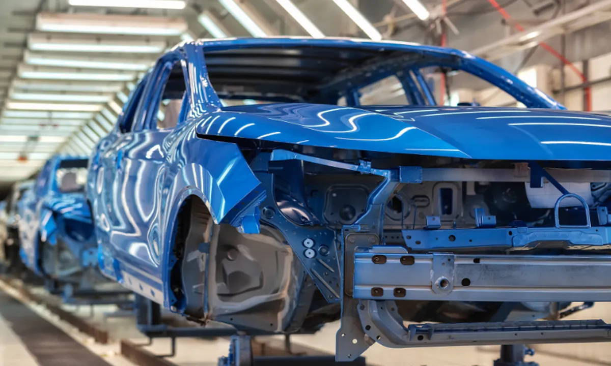
- Indústria Automotiva
Zinc die-cast bevel gears are widely used in automotive applications such as transmission systems, steering mechanisms, and differential drives. Their lightweight design, corrosion resistance, and high strength make them suitable for enduring continuous mechanical stress and environmental exposure. - Máquinas Industriais
In industrial machines, these gears are crucial components for power transmission in conveyor belts, mixers, and pumps. Their precise 1:1 ratio and durability ensure efficient motion transfer, even under heavy loads, while maintaining operational reliability. - Home Appliances
Zinc die-cast bevel gears are commonly used in home appliances like blenders, washing machines, and vacuum cleaners. Their smooth operation and resistance to wear allow for quiet, long-lasting functionality in devices subjected to regular and intensive use. - Robótica e Automação
These gears play a vital role in robotics and automated systems, where precise motion control is essential. Their ability to transmit power at right angles, combined with their compact size and durability, ensures efficient performance in complex robotic movements. - Aerospace and Defense
In aerospace and defense applications, zinc die-cast bevel gears are used in control systems and navigation mechanisms. Their lightweight nature and ability to withstand harsh environments make them ideal for maintaining functionality in extreme conditions. - Equipamentos médicos
Medical devices, such as imaging machines and surgical robots, rely on zinc die-cast bevel gears for precision and reliability. Their corrosion resistance and consistent performance under sterilization processes ensure they meet the stringent standards of medical applications.
 |  |
| Engrenagem cônica para a indústria automotiva | Engrenagem cônica para a indústria da robótica |
 | 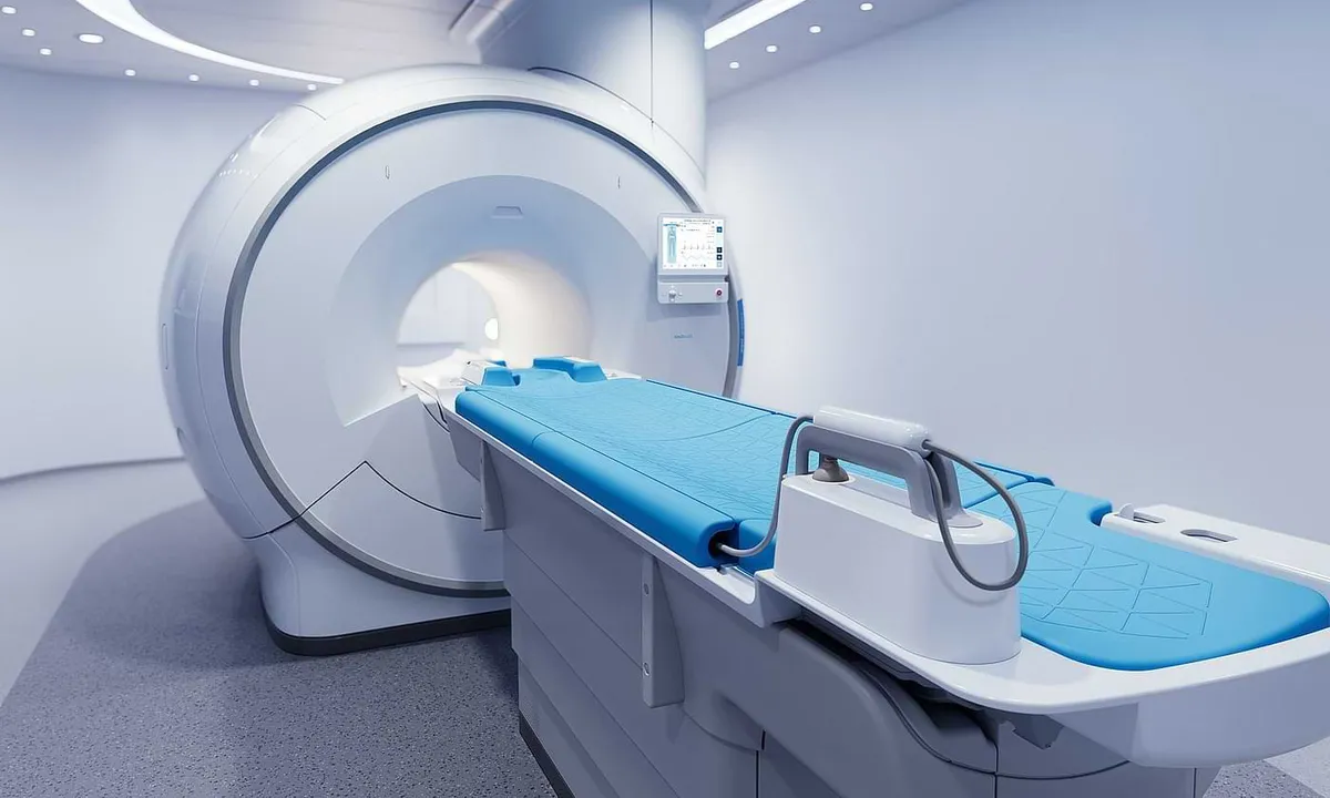 |
| Engrenagem cônica para a indústria aeroespacial | Bevel Gear for Medical Industry |
Engrenagem cônica versus engrenagem de esquadria
As engrenagens cônicas são um tipo de engrenagem cônica com dentes que se cruzam em um ângulo de 90 graus. Elas são projetadas para transmitir movimento e potência entre dois eixos perpendiculares entre si. As engrenagens cônicas são comumente usadas em uma ampla gama de aplicações mecânicas, incluindo máquinas industriais, sistemas automotivos e instrumentos de precisão.
Os dentes das engrenagens cônicas são cortados em um ângulo de 45 graus em relação ao eixo de rotação, permitindo que se encaixem de forma suave e eficiente. Essa geometria de dente exclusiva possibilita que as engrenagens cônicas mudem o sentido de rotação, mantendo uma relação de velocidade constante entre os eixos de entrada e saída.
Advantages of Miter Gears
Design compacto
Due to their perpendicular arrangement, miter gears allow for a more space-efficient power transmission system compared to other gear types.
High Efficiency
The precise meshing of the gear teeth ensures smooth and efficient transfer of motion and torque between the intersecting shafts. This high efficiency translates to reduced energy consumption and improved overall system performance.
Versatilidade
Miter gears are highly versatile and can be used in a wide range of applications across various industries. They are suitable for both low and high-speed applications, as well as for transmitting light to moderate loads.
Disadvantages of Miter Gears
Limited Load Capacity
Compared to other types of bevel gears, such as spiral bevel gears, miter gears have a relatively limited load capacity. The point contact between the gear teeth results in higher stress concentrations, which can lead to premature wear and reduced gear life under heavy loads.
Retaliação
Miter gears are prone to backlash, which refers to the clearance between the mating gear teeth. Backlash can cause positioning errors, vibrations, and noise in the gear system.
Alignment Sensitivity
Any misalignment between the intersecting shafts can lead to increased wear, vibration, and reduced gear life.
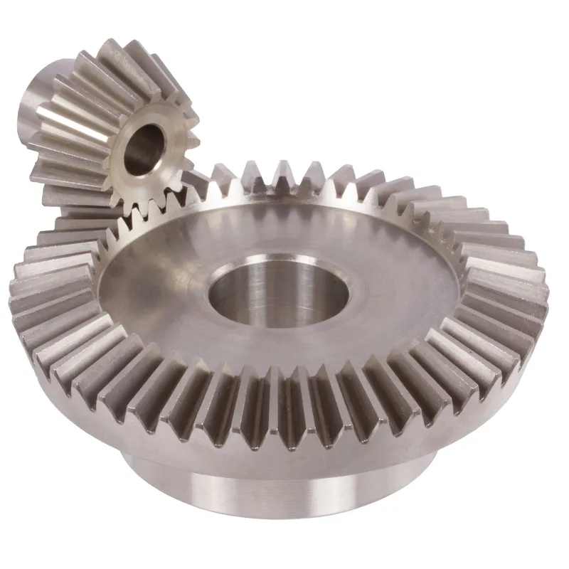
As engrenagens cônicas são um tipo de engrenagem mecânica que apresenta dentes em formato cônico, permitindo a transmissão de potência entre eixos que se cruzam em vários ângulos. Ao contrário das engrenagens de esquadria, que são limitadas a ângulos de 90 graus, as engrenagens cônicas oferecem maior flexibilidade na orientação dos eixos. Essas engrenagens são amplamente utilizadas em uma vasta gama de máquinas e aplicações onde a transmissão de potência entre eixos não paralelos é necessária.
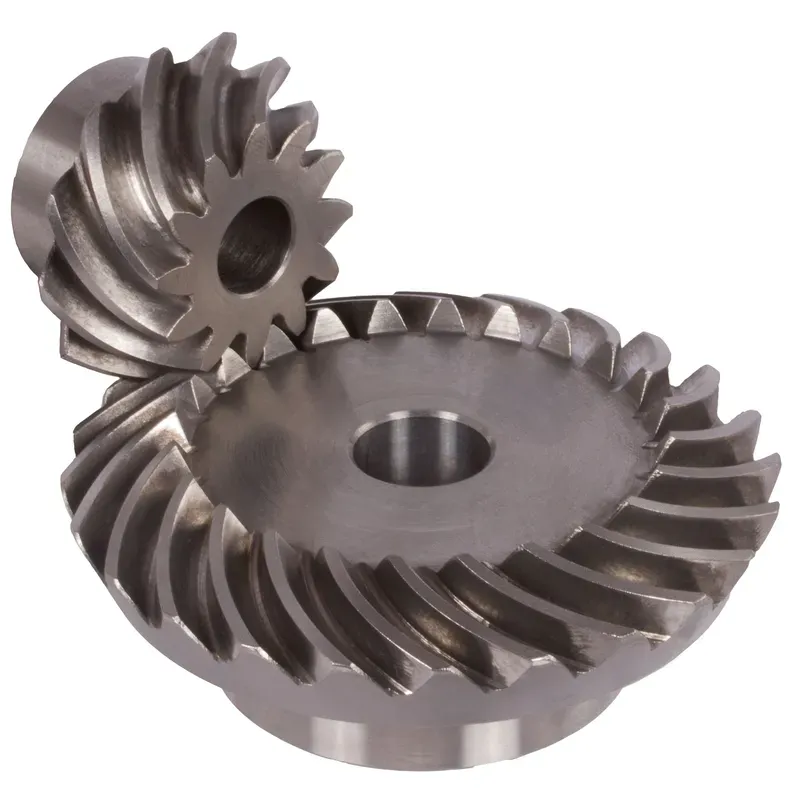
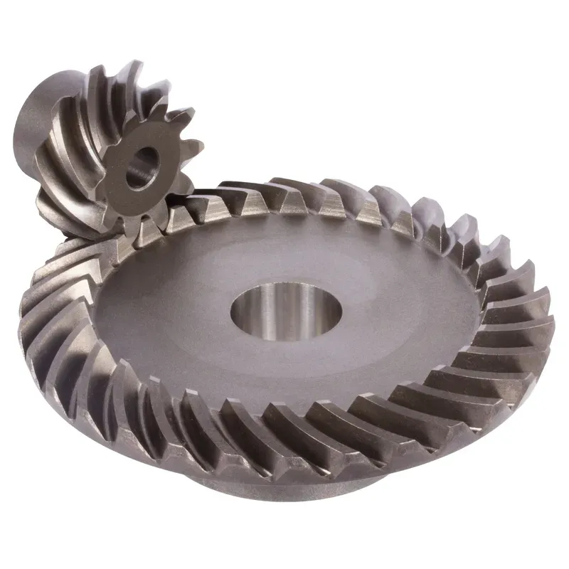
As engrenagens cônicas vêm em diferentes configurações, incluindo engrenagens cônicas retas, engrenagens cônicas espirais e engrenagens cônicas hipoides.
- As engrenagens cônicas retas possuem dentes cortados em linha reta na superfície do cone, enquanto as engrenagens cônicas helicoidais apresentam dentes curvos para uma operação mais suave e silenciosa.
- As engrenagens cônicas hipoides, uma variação das engrenagens cônicas espirais, possuem um eixo do pinhão deslocado para aumentar a capacidade de torque e reduzir o ruído.
Vantagens das Engrenagens Cônicas
Versatile Shaft Angles
Uma das principais vantagens das engrenagens cônicas é sua capacidade de transmitir potência entre eixos em vários ângulos, não se limitando apenas a 90 graus como as engrenagens de meia-esquadria.
Operação suave e silenciosa
Spiral bevel gears and hypoid bevel gears offer smoother and quieter operation compared to straight bevel gears. The curved teeth of spiral bevel gears provide a more gradual engagement, reducing vibration and noise.
Alta capacidade de torque
Engrenagens cônicas, especialmente as hipoides, são capazes de transmitir altas cargas de torque. O eixo do pinhão deslocado em engrenagens hipoides permite maiores áreas de contato dos dentes, aumentando sua capacidade de carga.
Design compacto
Bevel gears enable compact designs by allowing power transmission between intersecting shafts in a smaller space compared to other gear configurations.
Desvantagens das engrenagens cônicas
Complex Manufacturing
The manufacturing process for bevel gears, especially spiral and hypoid bevel gears, is more complex and costly compared to other gear types.
Higher Friction and Heat Generation
Due to the sliding action between the teeth, bevel gears are subject to higher friction compared to spur or helical gears.
Potential for Backlash
Engrenagens cônicas podem apresentar folga, que é a folga ou a folga entre os dentes da engrenagem. A folga pode resultar em precisão posicional reduzida e maior desgaste, principalmente em aplicações que exigem posicionamento preciso ou operação em baixa velocidade.
Limited Speed Ratios
While bevel gears offer versatility in shaft angles, they are limited in terms of achievable speed ratios compared to other gear types like worm gears.
Key Differences Between Miter Gears and Bevel Gears
While both miter gears and bevel gears are used to transmit power between intersecting shafts, they have distinct differences in design, functionality, and mechanical advantage.
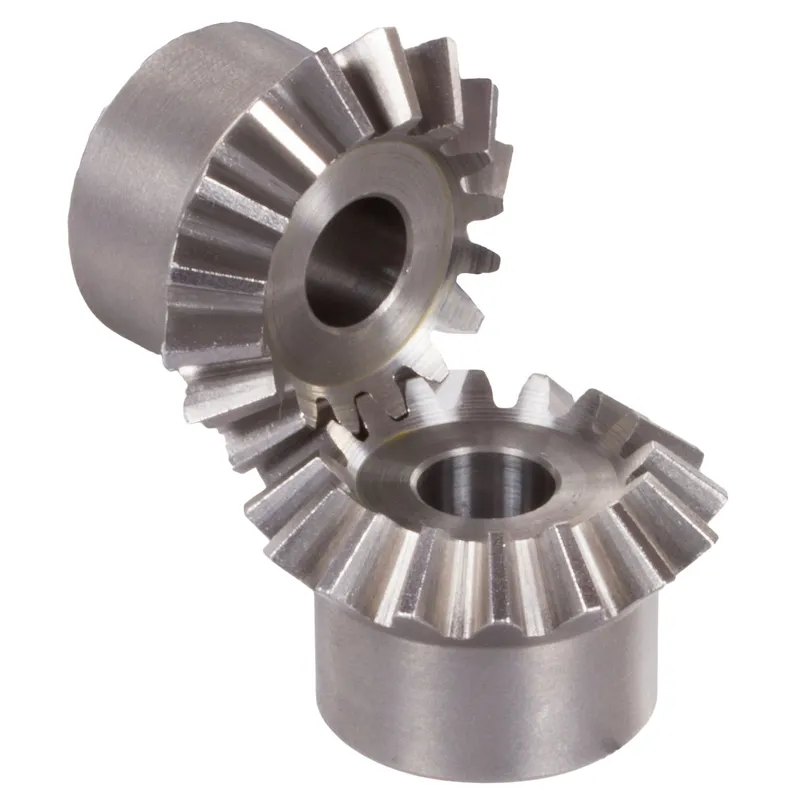
Projeto
Miter gears are a specific type of bevel gear designed to operate with shafts at a 90-degree angle.
In contrast, bevel gears can be designed for any angle between 0 and 180 degrees, providing greater flexibility in shaft positioning.
Functional
Miter gears are typically used in applications requiring a 90-degree change in direction of motion or power transmission. They are commonly found in hand tools, automotive differentials, and industrial machinery.
Bevel gears, on the other hand, offer more versatility in terms of shaft angles and are used in a wider range of applications, such as automotive drivetrains, aircraft control systems, and power transmission in various machines.
Mechanical Advantage
Miter gears generally have a 1:1 gear ratio, meaning they do not provide any mechanical advantage in terms of speed or torque.
Bevel gears, however, can be designed with different gear ratios, allowing for speed reduction or torque multiplication, depending on the application requirements.
Load Requirements
The load capacity of miter gears and bevel gears varies based on factors such as material, surface hardness, and tooth profile. Generally, bevel gears can handle higher loads compared to miter gears due to their ability to distribute stress more evenly along the tooth surface.
Space Constraints
Miter gears are more compact and require less space for their installation, making them suitable for applications with limited space. Bevel gears, while more versatile in terms of shaft angles, may require more space to accommodate their larger size and angular positioning.
Informação adicional
| Editado por | Yjx |
|---|
Produtos relacionados
-
Brass Bevel Gears Ratio 1.5:1 Straight-Tooth System
-
Engrenagens cônicas espirais de aço com relação de 2,5:1 e sistema de dentes espirais.
-
Engrenagens cônicas espirais de aço com relação de dentes espirais 4:1
-
Steel Miter Bevel Gears Ratio 1:1 Straight Tooth System
-
Engrenagens cônicas espirais de aço com relação de 2:1 e sistema de dentes espirais.


