WPWDA Worm Gear Reducers/Worm Gearbox
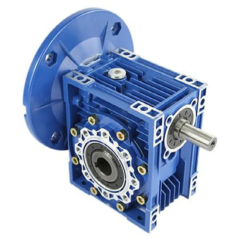
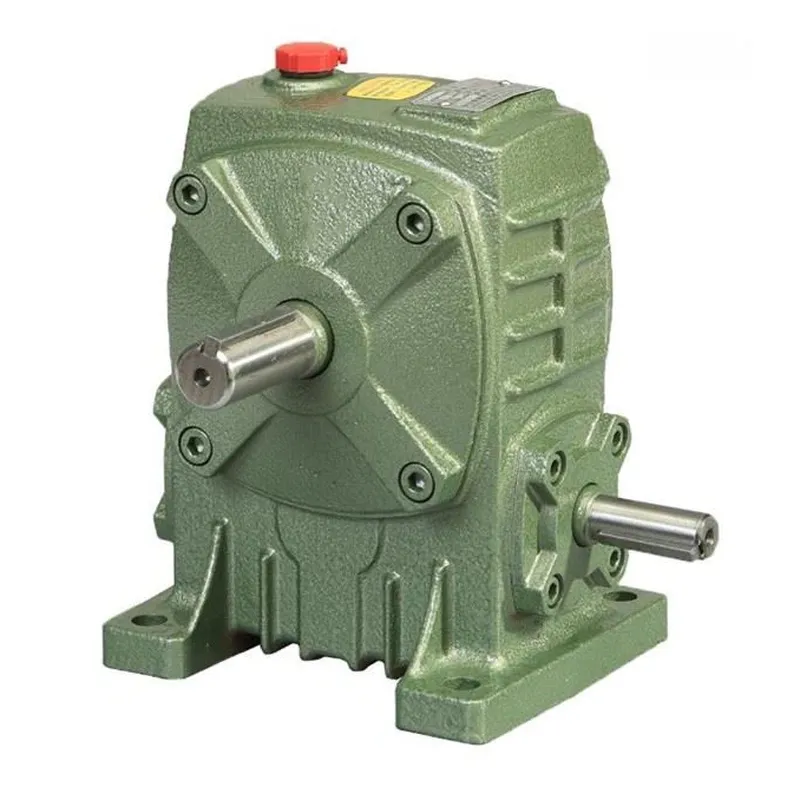
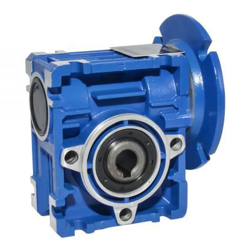
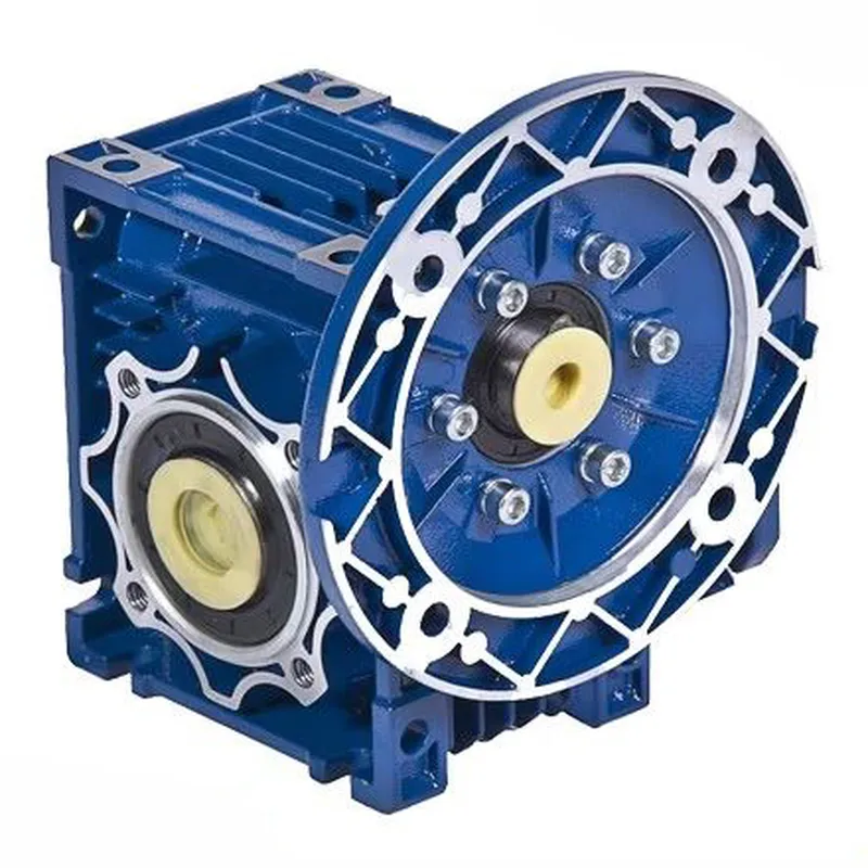
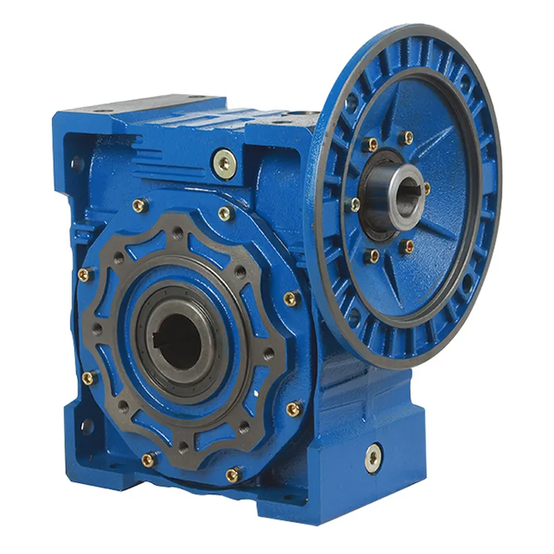
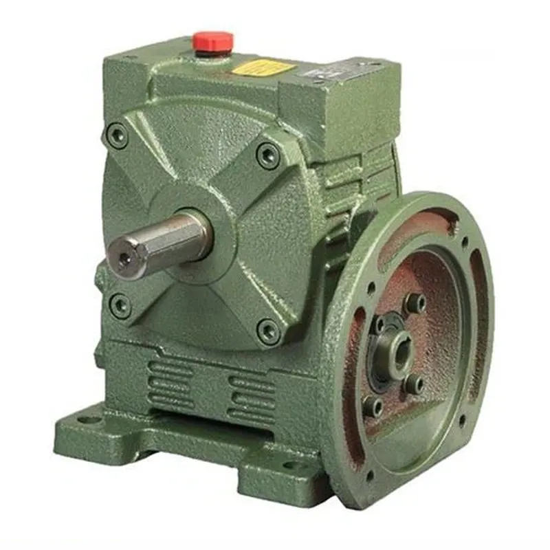
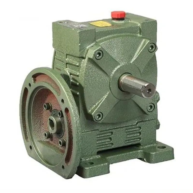
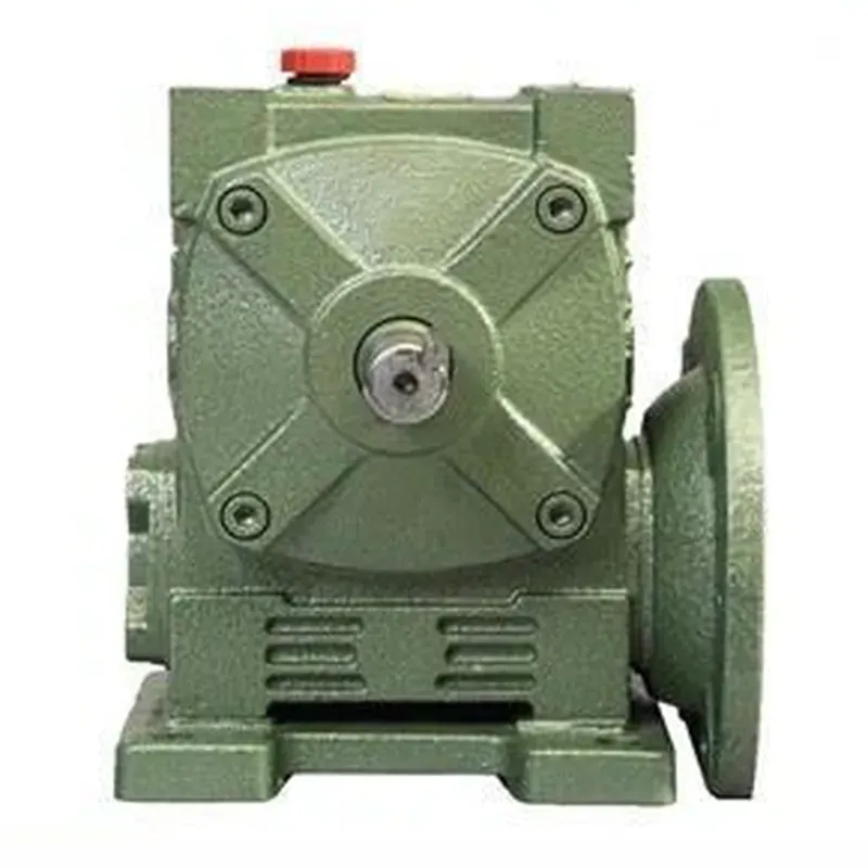
WPWDA worm gear reducers, also known as worm gearboxes, are mechanical devices designed for efficient power transmission in industrial applications. They feature a worm (a screw-like gear) meshing with a worm wheel, enabling high torque output and significant speed reduction in a compact design. The WPWDA worm gearbox specifically includes a lower input flange configuration, with options for solid or hollow output shafts, allowing flexible mounting (horizontal or vertical).
WPWDA worm gear reducers, also known as worm gearboxes, are mechanical devices designed for efficient power transmission in industrial applications. They feature a worm (a screw-like gear) meshing with a worm wheel, enabling high torque output and significant speed reduction in a compact design. The WPWDA worm gearbox specifically includes a lower input flange configuration, with options for solid or hollow output shafts, allowing flexible mounting (horizontal or vertical).
Constructed with cast iron housing and single-stage worm gears, these worm gear speed reducers offer durability, self-locking capabilities under certain conditions, and high reduction ratios (e.g., 1/10 to 1/60). They are widely used in conveyors, packaging machines, and other systems requiring reliable, quiet operation with minimal space.
WPWDA Worm Gear Reducer Specifications
| Type: | WPWDA Worm Gearbox/ Worm Gear Speed Reducer |
| Model: | 40,50,60,70,80,100,120,135,155,175,200,250 |
| Ratio: | 10,15,20,25,30,40,50,60 |
| Color: | Blue/Green/Black/Customized |
| Material: | Housing: Die-Cast Iron cast |
| Worm Gear: Copper-9-4# | |
| Worm: 20CrMn Ti with carburizing and quenching, surface hardness is 56-62HRC | |
| Shaft: chromium steel-45# | |
| Packing: | Carton and Wooden Case |
| Bearing: | C&U/SKF/HRB, or on customer request |
| Seal: | NAK/SKF/KSK, or on customer request |
| Warranty: | 12Months |
| Input Power: | 0.12kw~15kw |
| Usages: | Plastics, metallurgy, beverages, mining, lifting and transportation, chemical construction, and so on. |
| IEC Flange: | B5 |
| Lubricant: | Synthetic & Mineral |
WPWDA Worm Gearbox Dimensions
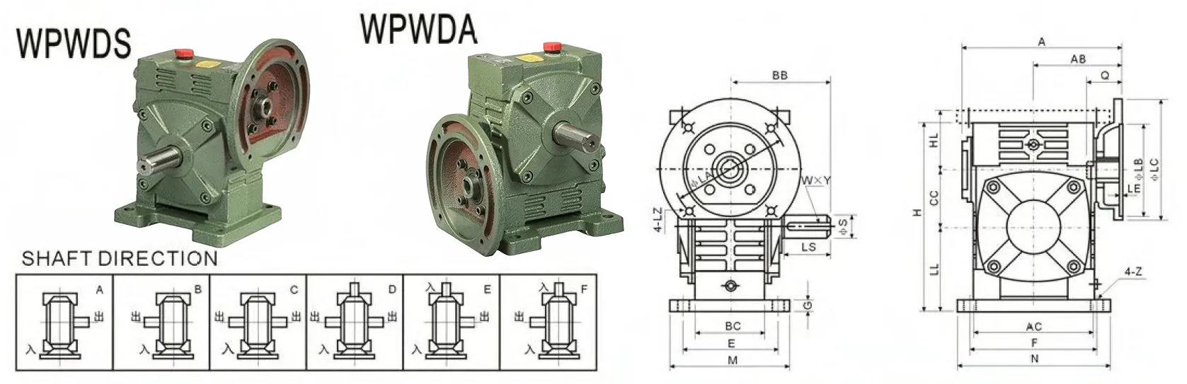
| Model | Input Power(kW) | Ratio | A | AB | BB | AC | BC | CC | HL | LL | H | M | N | E | F | G | Z |
|---|---|---|---|---|---|---|---|---|---|---|---|---|---|---|---|---|---|
| 40 | 0.12 | 1/5 1/10 1/20 1/25 1/30 1/40 1/50 1/60 | 135 | 75 | 74 | 95 | 61 | 40 | 45 | 60 | 135 | 100 | 130 | 80 | 110 | 10 | 10 |
| 50 | 0.18 | 151 | 83 | 97 | 111 | 68 | 50 | 50 | 80 | 165 | 120 | 140 | 95 | 110 | 15 | 12 | |
| 60 | 0.37 | 167 | 91 | 112 | 127 | 76 | 60 | 60 | 93 | 195 | 130 | 150 | 105 | 120 | 18 | 12 | |
| 70 | 0.37 | 200 202 | 109 111 | 131 | 152 | 86 | 70 | 73 | 108 | 233 | 150 | 190 | 115 | 150 | 18 | 15 | |
| 80 | 0.75 1.5 | 225 | 125 | 142 | 169 | 102 | 80 | 83 | 123 | 268 | 170 | 220 | 135 | 180 | 18 | 15 | |
| 100 | 1.5 | 280 | 148 | 169 | 216 | 117 | 100 | 100 | 150 | 330 | 190 | 270 | 155 | 220 | 20 | 15 | |
| 120 | 2.2 2.2 | 333 | 181 | 190 | 256 | 124 | 120 | 120 | 180 | 395 | 230 | 320 | 180 | 260 | 25 | 18 | |
| 135 | 3.0 4.0 | 375 | 202 | 210 | 296 | 147 | 135 | 135 | 215 | 455 | 250 | 350 | 200 | 290 | 30 | 18 | |
| 155 | 5.5 | 448 | 247 | 253 | 345 | 185 | 155 | 135 | 235 | 493 | 280 | 380 | 220 | 320 | 32 | 21 | |
| 175 | 5.5 7.5 | 481 | 262 | 255 | 374 | 192 | 175 | 160 | 260 | 558 | 310 | 410 | 250 | 350 | 37 | 21 | |
| 200 | 7.5 | 543 | 285 | 319 | 412 | 230 | 200 | 175 | 290 | 620 | 355 | 445 | 290 | 390 | 45 | 24 | |
| 250 | 11.0 15.0 | 615 | 330 | 385 | 500 | 285 | 250 | 200 | 350 | 750 | 460 | 560 | 380 | 480 | 50 | 28 |
| Flange | Input Hole | Output shaft | Weight | ||||||||
|---|---|---|---|---|---|---|---|---|---|---|---|
| LA | LB | LC | LE | LZ | Q | U | T×V | LS | S | W×Y | (kW) |
| 115 | 95 | 140 | 4 | M8 | 31 | 11 | 4×12.8 | 28 | 14 | 5×3 | 5 |
| 115 | 95 | 140 | 4 | M8 | 31 | 11 | 4×12.8 | 40 | 17 | 5×3 | 8 |
| 130 | 110 | 160 | 4 | M8 | 33 | 14 | 5×16.3 | 50 | 22 | 7×4 | 12.5 |
| 165 | 130 | 200 | 4 | M10 | 42 | 19 | 6×21.8 | 60 | 28 | 7×4 | 17 |
| 165 | 130 | 200 | 4.5 | M10 | 48 | 19 | 6×21.8 | 65 | 32 | 10×4.5 | 26 |
| 165 | 130 | 200 | 4.5 | M10 | 52 | 24 | 8×27.3 | 75 | 38 | 10×4.5 | 41.5 |
| 215 | 180 | 250 | 5 | M12 | 63 | 28 | 8×31.3 | 85 | 45 | 12×4.5 | 60 |
| 215 | 180 | 250 | 5 | M12 | 63 | 28 | 8×31.3 | 95 | 55 | 16×6 | 90 |
| 265 | 230 | 300 | 5 | M12 | 83 | 38 | 10×41.3 | 110 | 60 | 18×7 | 118 |
| 265 | 230 | 300 | 5 | M12 | 83 | 38 | 10×41.3 | 110 | 65 | 18×7 | 167 |
| 300 | 250 | 350 | 6 | M16 | 114 | 42 | 12×45.3 | 125 | 70 | 20×7.5 | 237 |
| 300 | 250 | 350 | 6 | M16 | 114 | 42 | 12×45.3 | 155 | 90 | 25×9 | 395 |
WPWDA Worm Reducer Gearbox Part Structure
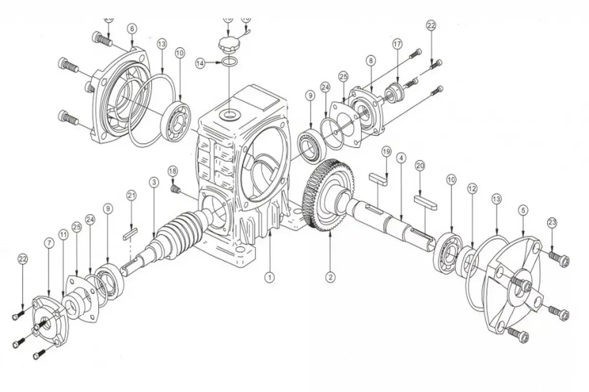
| 1 | Frame | 13 | O Ring |
| 2 | Worm Wheel | 14 | O Ring |
| 3 | Worm Shaft | 15 | Oil Hole Cover |
| 4 | Output Shaft | 16 | Pin |
| 5 | Output Shaft Cover | 17 | Oil Guage |
| 6 | Output Shaft Cover | 18 | Oil Plug |
| 7 | Input Shaft Cover | 19 | Key |
| 8 | Input Shaft Cover | 20 | Key |
| 9 | Bearing | 21 | Key |
| 10 | Bearing | 22 | Intl.hex Screw |
| 11 | Oil Seal | 23 | Intl.hex Screw |
| 12 | Oil Seal | 24 | Shim |
WPWDA Worm Gear Gearbox Advantages
- High Torque Output
WPWDA worm gear gearboxes deliver exceptional torque for heavy-duty applications like conveyors and mixers. Their worm and wheel design ensures efficient power transfer, enabling reliable performance in demanding industrial environments with consistent high-torque output and minimal energy loss. - Compact Design
These worm reducer gearboxes feature a space-saving structure, ideal for applications with limited installation space. The compact cast iron housing and single-stage worm gear system allow seamless integration into machinery, maintaining efficiency without compromising on strength or durability in tight setups. - High Reduction Ratios
WPWDA worm gear reducers offer significant speed reduction, with ratios from 1/10 to 1/60. This allows precise control over output speed, making them suitable for applications requiring slow, controlled movements, such as packaging equipment or material handling systems, ensuring operational accuracy. - Self-Locking Capability
Under specific conditions, these worm drive gearboxes provide self-locking, preventing back-driving. This feature enhances safety and stability in applications like hoists or lifts, where maintaining position without external braking is critical, ensuring reliable operation and reducing maintenance needs. - Durable Construction
Built with robust cast iron housing and precision-engineered worm gears, WPWDA worm gear speed reducers withstand harsh industrial conditions. Their durability ensures long service life, reducing downtime and maintenance costs in applications like manufacturing, mining, or heavy machinery operations. - Quiet Operation
The worm gear design minimizes noise and vibration during operation. This makes worm and wheel gearboxes ideal for environments requiring low noise levels, such as food processing or automated assembly lines, ensuring worker comfort and compliance with noise regulations.
WPWDA Worm and Wheel Gearbox Applications
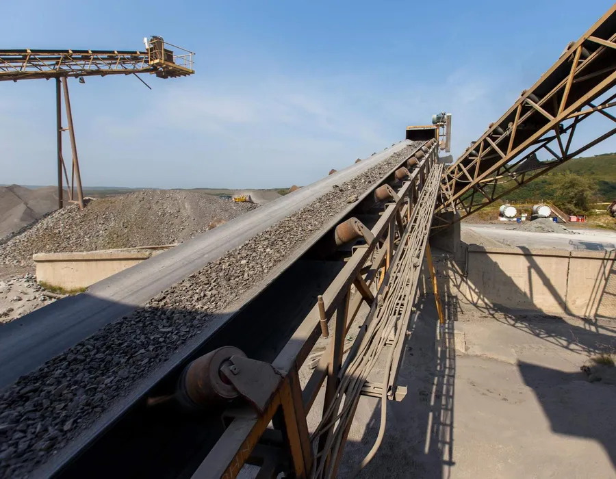
- Conveyor Systems
WPWDA worm and wheel gearboxes are widely used in conveyor systems for material handling in industries like manufacturing and logistics. Their high torque and precise speed control ensure smooth, reliable transport of goods, enhancing efficiency in automated production lines. - Packaging Machinery
These right angle worm gearboxes drive packaging equipment, such as filling and sealing machines, in food, beverage, and pharmaceutical industries. Their compact design and high reduction ratios enable precise, consistent movements, ensuring accurate packaging processes with minimal maintenance and space requirements. - Hoists and Lifts
WPWDA worm reducer gearboxes are ideal for hoisting equipment due to their self-locking capability, which prevents back-driving. This ensures safe, stable operation in applications like construction cranes or warehouse lifts, providing reliable load control and enhanced safety for heavy lifting tasks. - Mixing Equipment
In chemical, food, and pharmaceutical processing, these worm gear reducers power mixers and agitators. Their high torque output and durable construction handle viscous materials effectively, ensuring consistent mixing performance while withstanding demanding conditions and maintaining operational reliability. - Automated Assembly Lines
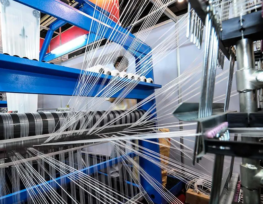
WPWDA worm reduction gearboxes support automated assembly systems in automotive and electronics manufacturing. Their quiet operation and precise speed control facilitate smooth, accurate component placement, improving production efficiency and reducing noise in high-precision, repetitive-task environments. - Textile Machinery
These worm gear speed reducers are employed in textile equipment, such as spinning and weaving machines. Their ability to deliver high torque at low speeds ensures precise control over fabric production processes, enhancing product quality and operational efficiency in textile manufacturing facilities.
 |  |
| Worm Gearbox for Conveyor Equipment | Worm Gearbox for Textile Industry |
 |  |
| Worm Gearbox for Food and Beverage Industry | Worm Gearbox for Construction Industry |
WPWDA Worm Gear Reducer Installation Steps
- Preparation and Inspection
Before installation, verify that the WPWDA worm gear reducer’s specifications match the application requirements. Inspect the gearbox for damage, ensure all components are included, and confirm the mounting surface is clean, level, and capable of supporting the unit’s weight and operational loads. - Align Mounting Position
Position the gearbox on the designated mounting surface, ensuring proper alignment with the driven equipment. Use a level to check horizontal or vertical orientation, depending on the application. Proper alignment prevents stress on the shaft and ensures efficient power transmission. - Secure the Gearbox
Fasten the worm gear reducer gearbox to the mounting surface using appropriate bolts and torque specifications as per the manual’s guidelines. Ensure bolts are evenly tightened to avoid misalignment. Check for stability to prevent vibration or movement during operation, ensuring long-term reliability. - Connect Input and Output Shafts
Align the input shaft with the driving motor and the output shaft with the driven equipment. Use flexible couplings to accommodate minor misalignments. Verify shaft alignment with precision tools to minimize wear and ensure smooth power transfer during operation. - Lubrication Check
Verify the gearbox is filled with the recommended lubricant to the specified level. Check for leaks and ensure the oil sight glass or dipstick indicates proper levels. Adequate lubrication reduces friction, prevents overheating, and extends the service life of the worm gear reducer. - Test Run and Adjustment
Start the system at low speed to test the worm drive reduction gearbox operation. Monitor for unusual noises, vibrations, or overheating. Adjust alignment or lubrication if necessary. Gradually increase speed to full operation, ensuring the gearbox performs reliably under load conditions.
Additional information
| Edited by | Yjx |
|---|