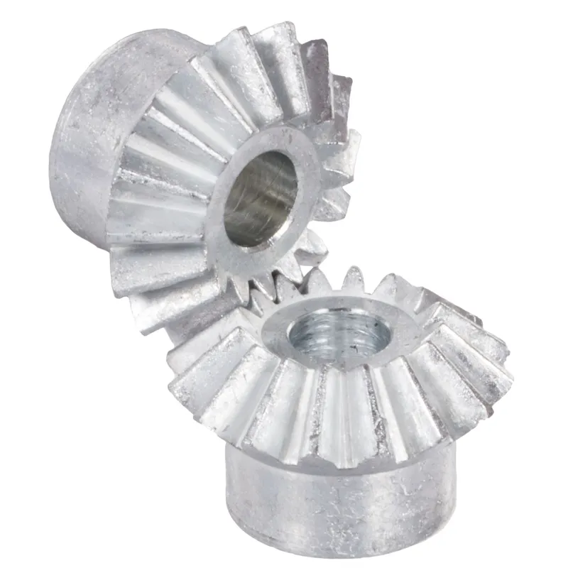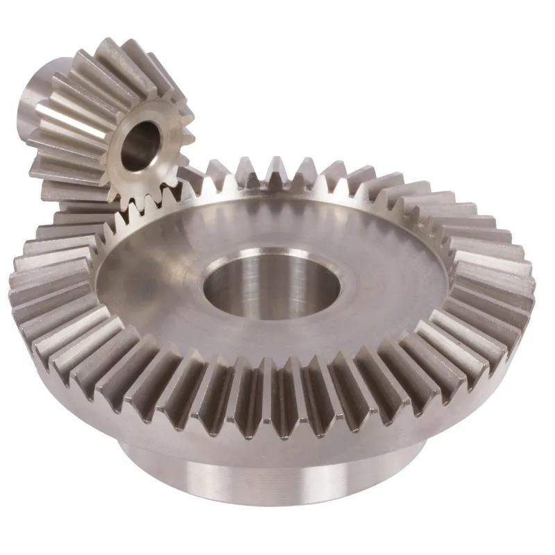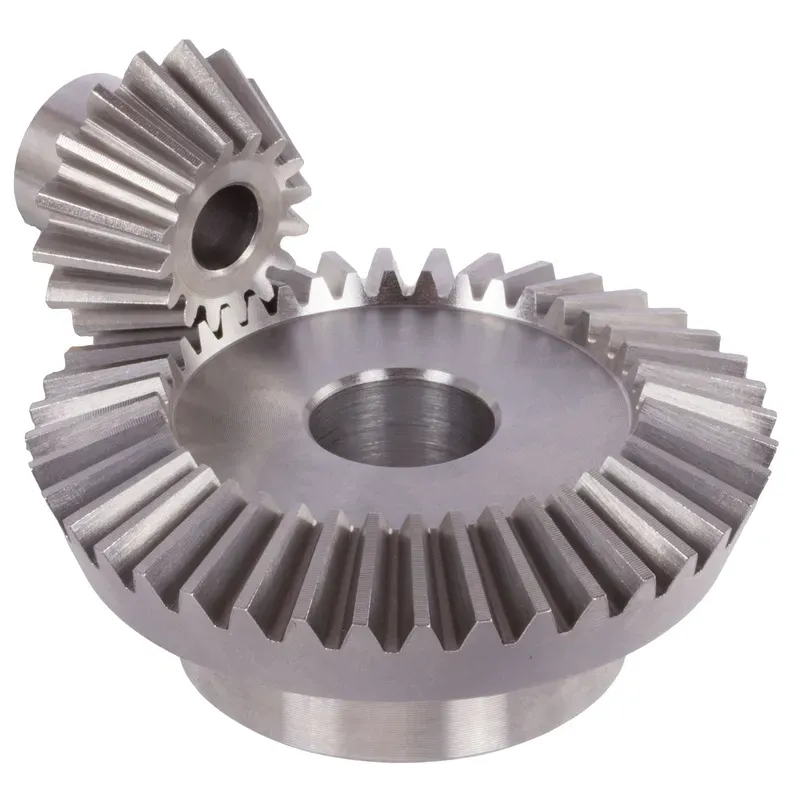
Steel Straight Bevel Gears Ratio 2.5:1 Straight Tooth System
The steel straight bevel gears ratio 2.5:1 straight tooth system refers to a mechanical gear arrangement used to transmit rotational motion and torque between intersecting shafts, typically at a 90-degree angle. Made from steel, they provide excellent durability, resistance to wear, and the capacity to handle higher loads compared to gears made from softer materials. These steel bevel gears are commonly used in industrial machinery, automotive differentials, and power transmission systems where precise and reliable angular motion transfer is required.
The steel straight bevel gears ratio 2.5:1 straight tooth system refers to a mechanical gear arrangement used to transmit rotational motion and torque between intersecting shafts, typically at a 90-degree angle. These gears have a 2.5:1 gear ratio, meaning the larger gear (driven gear) completes one full revolution for every 2.5 revolutions of the smaller gear (driver gear). This ratio is ideal for applications requiring a moderate reduction in speed while increasing torque.
The term "straight bevel gears" signifies that the teeth are cut straight along the gear's conical surface, unlike spiral bevel gears, which have curved teeth. Straight bevel gears are simpler in design, cost-effective, and well-suited for low-speed and moderate-load applications. Made from steel, they provide excellent durability, resistance to wear, and the capacity to handle higher loads compared to gears made from softer materials. These gears are commonly used in industrial machinery, automotive differentials, and power transmission systems where precise and reliable angular motion transfer is required.
Steel Straight Bevel Gear Ratio 2.5:1
| 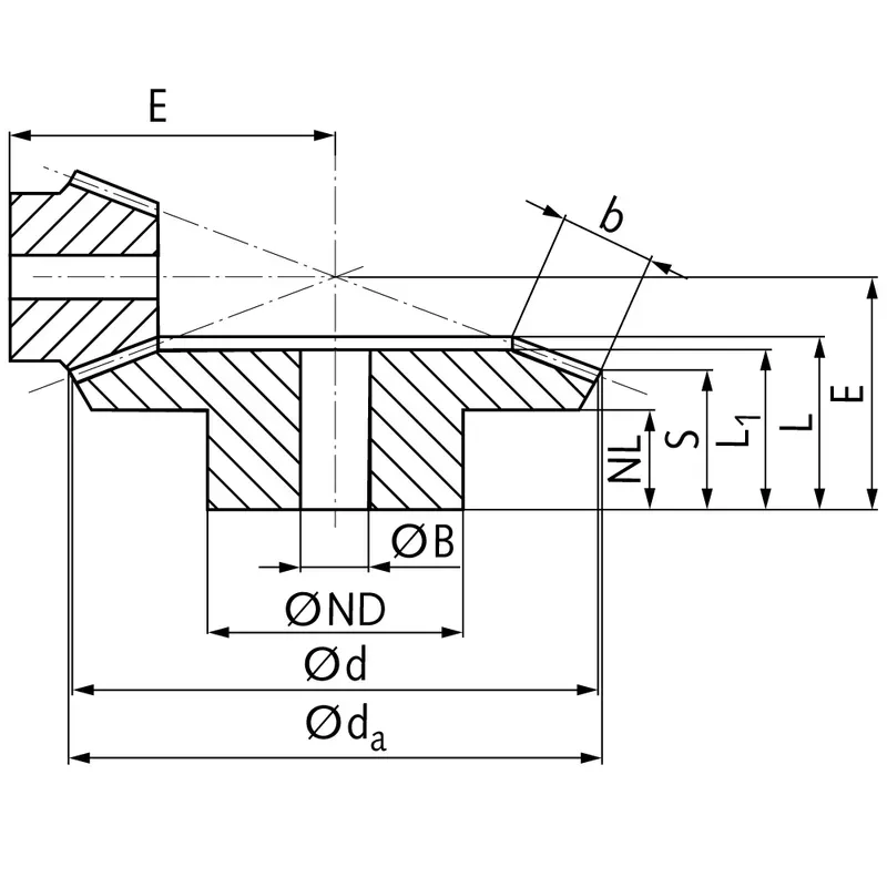 |
| Module | Number of teeth | da | d | ND | NL | L1 | L | S | b | BH7 | E | Torque* | Weight |
| mm | mm | mm | mm | mm | mm | mm | mm | mm | mm | Ncm | g | ||
| 0,5 | 20 | 11,3 | 10 | 8 | 4,0 | 7 | 7,6 | 4,9 | 3 | 4 | 17,1 | 0,018 | 3 |
| 0,5 | 50 | 25,2 | 25 | 14 | 5,0 | 7 | 7,8 | 6,8 | 3 | 4 | 11,5 | 0,045 | 10 |
| 1 | 16 | 18,6 | 16 | 13 | 7,4 | 13 | 14,4 | 8,5 | 6,5 | 5 | 28 | 0,090 | 13 |
| 1 | 40 | 40,5 | 40 | 25 | 9,0 | 13 | 14,8 | 12,6 | 6,5 | 8 | 20 | 0,225 | 65 |
| 1,5 | 16 | 27,9 | 24 | 18 | 8,8 | 18 | 19,5 | 10,8 | 9,7 | 8 | 40 | 0,32 | 36 |
| 1,5 | 40 | 60,7 | 60 | 40 | 10,0 | 17 | 20,1 | 16,9 | 9,7 | 15 | 28 | 0,80 | 220 |
| 1,5 | 18 | 30,9 | 27 | 20 | 10,8 | 21 | 22,9 | 13,0 | 10,9 | 8 | 46 | 0,47 | 54 |
| 1,5 | 45 | 68,2 | 67,5 | 50 | 12,0 | 20 | 24,1 | 20,4 | 10,9 | 15 | 33 | 1,18 | 370 |
| 2 | 16 | 35,9 | 32 | 20 | 9,0 | 25 | 26,4 | 12,7 | 15 | 10 | 52 | 0,84 | 76 |
| 2 | 40 | 81,5 | 80 | 50 | 15,0 | 29 | 32,7 | 27,9 | 15 | 20 | 42 | 2,10 | 650 |
| 2 | 18 | 39,8 | 36 | 30 | 11,8 | 26 | 27,4 | 13,8 | 15 | 10 | 58 | 1,18 | 133 |
| 2 | 45 | 91,5 | 90 | 60 | 18,0 | 30 | 33,8 | 28,9 | 15 | 25 | 45 | 2,95 | 830 |
| 2,5 | 16 | 44,8 | 40 | 30 | 13,0 | 32 | 34,1 | 15,9 | 20 | 10 | 65 | 5,0 | 180 |
| 2,5 | 40 | 101,9 | 100 | 60 | 15,0 | 29 | 33,8 | 27,4 | 20 | 25 | 45 | 12,5 | 1000 |
| 2,5 | 18 | 49,8 | 45 | 30 | 15,75 | 36 | 37,9 | 19,7 | 20 | 10 | 75 | 7,1 | 240 |
| 2,5 | 45 | 114,4 | 112,5 | 70 | 15,0 | 28 | 33,4 | 26,9 | 20 | 25 | 47 | 17,8 | 1200 |
| 3 | 16 | 53,8 | 48 | 40 | 13,6 | 37 | 38,8 | 16,1 | 25 | 15 | 75 | 9,0 | 310 |
| 3 | 40 | 122,3 | 120 | 60 | 16,0 | 32 | 36,8 | 28,9 | 25 | 25 | 50 | 22,5 | 1400 |
| 3 | 18 | 59,8 | 54 | 40 | 11,7 | 36 | 38,4 | 15,7 | 25 | 15 | 82 | 12,8 | 380 |
| 3 | 45 | 137,3 | 135 | 70 | 18,0 | 34 | 39,0 | 30,9 | 25 | 30 | 55 | 32,0 | 1900 |
| 4 | 16 | 71,8 | 64 | 50 | 12,0 | 41 | 43,8 | 16,5 | 30 | 20 | 95 | 20,9 | 600 |
| 4 | 40 | 163,1 | 160 | 80 | 20,0 | 40 | 46,4 | 36,9 | 30 | 30 | 65 | 52,3 | 3400 |
| 4 | 18 | 79,7 | 72 | 50 | 13,8 | 44 | 46,8 | 19,5 | 30 | 20 | 108 | 29,3 | 800 |
| 4 | 45 | 183,0 | 180 | 90 | 20,0 | 43 | 49,6 | 39,9 | 30 | 30 | 72 | 73,3 | 4900 |
| 5 | 18 | 99,6 | 90 | 60 | 16,5 | 57 | 60,8 | 24,4 | 40 | 25 | 135 | 61,0 | 1560 |
| 5 | 45 | 228,8 | 225 | 100 | 20,0 | 50 | 57,8 | 44,8 | 40 | 40 | 85 | 152,5 | 9080 |
Steel Straight Bevel Gear Design Features
- Straight Tooth Configuration
Steel straight bevel gears feature teeth that are cut straight along the gear’s conical surface. This design allows for smooth engagement between the teeth when transferring power between intersecting shafts. The simplicity of the tooth structure makes these gears easier to manufacture and maintain. - Conical Gear Shape
The conical shape of the gear provides an efficient method to transmit motion between non-parallel shafts, typically intersecting at 90 degrees. This design ensures accurate alignment of rotational axes, making it suitable for a wide range of applications requiring angular motion transfer. - Material Strength and Durability
Constructed from high-quality steel, these steel bevel gears offer exceptional durability and resistance to wear. Steel’s high tensile strength allows these gears to handle heavy loads and operate reliably in demanding conditions, making them ideal for industrial and mechanical uses. - High Torque Transmission Capability
The robust design of straight bevel gears enables the efficient transmission of high torque. This feature is especially valuable in applications where significant force needs to be transferred, such as in automotive differentials or heavy machinery power systems. - Customizable Gear Ratios
Steel straight bevel gears can be designed with various gear ratios, such as 2.5:1, to meet specific engineering requirements. The ability to tailor the gear ratio ensures optimal performance in speed reduction or torque amplification for different operational needs. - Cost-Effective Manufacturing
The straightforward design of straight bevel gears simplifies the manufacturing process compared to more complex gear types like spiral bevel gears. This simplicity reduces production costs, making steel straight bevel gears an economical solution for industries requiring reliable and efficient power transmission.

Straight Bevel Gear Manufacturing Process
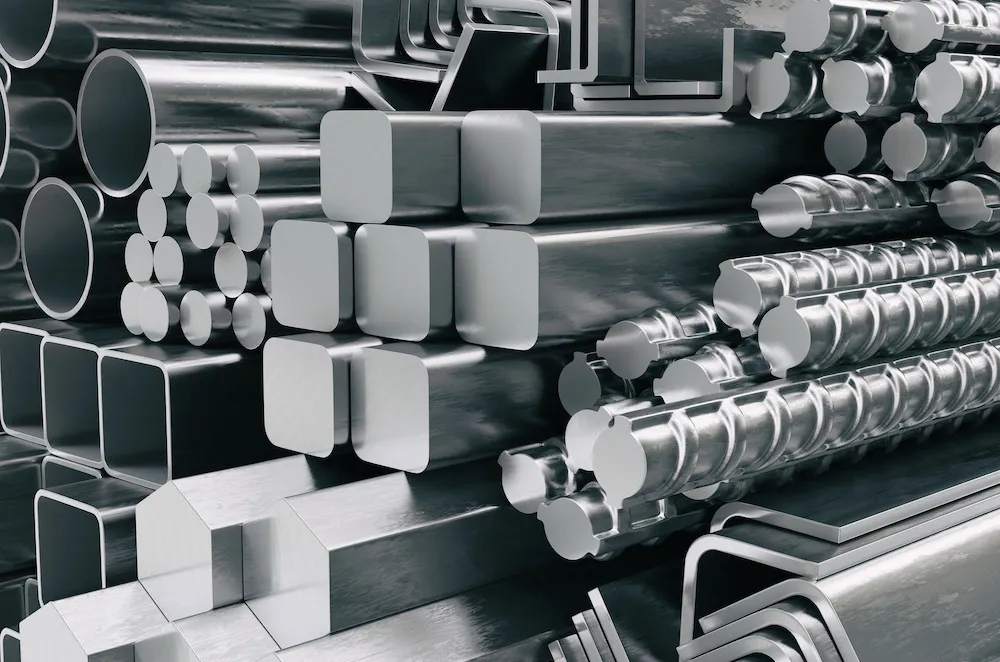
- Material Selection and Preparation
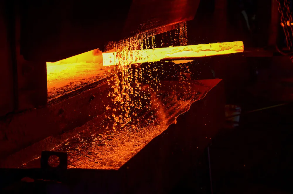
The process begins with selecting high-quality steel, which is known for its strength, durability, and wear resistance. The steel is then cut into the required size and shape, ensuring it meets the specifications of the gear design. - Forging or Casting the Gear Blank
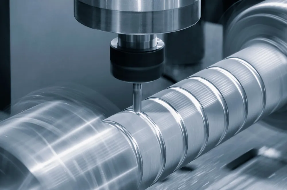
The steel is either forged or cast into a gear blank, which is the rough, preliminary shape of the gear. This step provides a solid foundation for the subsequent machining processes and ensures the gear can withstand high loads. - Precision Machining of the Gear Blank
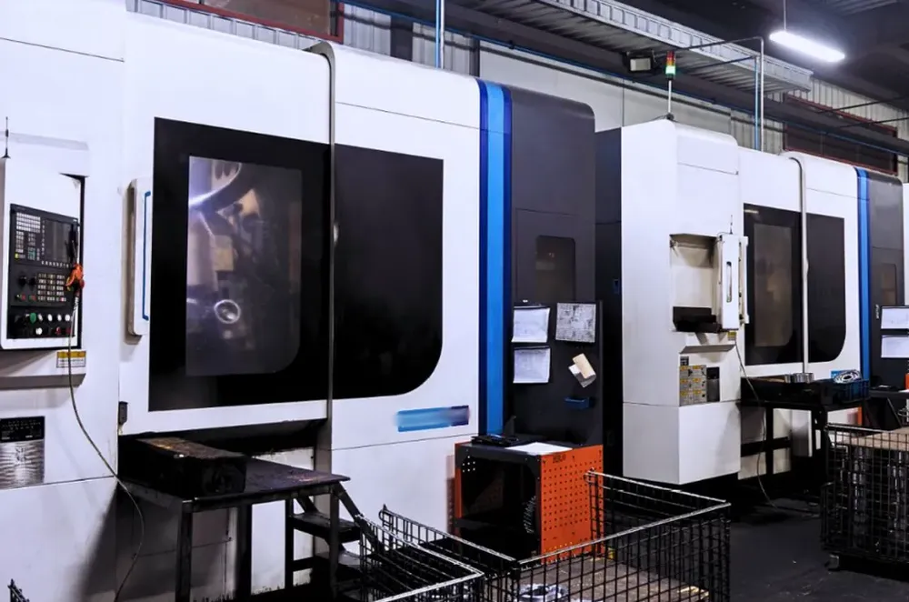
The gear blank undergoes precision machining to achieve the desired dimensions and tolerances. This step typically involves turning and milling processes to prepare the blank for the addition of teeth and other features. - Cutting the Gear Teeth
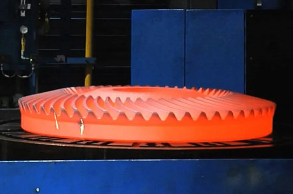
The teeth are cut onto the conical surface of the gear blank using specialized machines such as bevel gear generators or milling machines. The straight tooth profile is carefully shaped to ensure accurate meshing and efficient power transmission. - Heat Treatment for Strength Enhancement
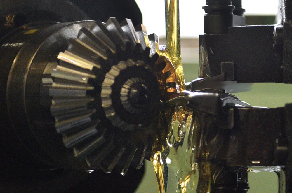
The gear undergoes heat treatment processes such as carburizing, quenching, and tempering to improve its hardness and strength. These processes enhance the gear’s wear resistance and durability, making it suitable for heavy-duty applications. - Grinding and Finishing the Gear Teeth
After heat treatment, the gear teeth are ground and finished to achieve a smooth surface and precise dimensions. This step ensures minimal friction during operation and enhances the overall efficiency and lifespan of the gear. - Quality Inspection and Testing
The manufactured gear is subjected to rigorous quality inspections and testing. This includes checking for dimensional accuracy, tooth alignment, and material integrity to ensure the gear meets all performance and safety standards. - Surface Treatment and Coating
To further enhance durability and corrosion resistance, the gear may undergo surface treatments such as phosphating, black oxide coating, or nitriding. These treatments protect the gear from environmental factors and extend its operational life. - Assembly and Final Application Fit
The finished gear is assembled with its mating components to ensure proper alignment and function. This step includes testing the gear in its intended application to confirm smooth operation and reliable power transmission under real-world conditions.
 |  |  |
 |  |  |
Steel Straight Bevel Gear Maintenance
- Regular Lubrication
Proper lubrication is essential to reduce friction and minimize wear between the gear teeth. Use high-quality lubricants suitable for the operating conditions and ensure consistent application. Regularly check and replenish the lubricant to maintain optimal performance and prevent overheating or premature failure. - Inspection for Wear and Damage
Conduct routine inspections to identify any signs of wear, cracks, or pitting on the gear teeth. Any irregularities should be addressed immediately to prevent further damage and ensure reliable operation. Using magnification tools can help detect micro-damage early. - Alignment Checks and Adjustments
Ensure the bevel gears remain correctly aligned during operation to avoid uneven wear and excessive stress on the teeth. Misalignment can lead to noise, vibration, and reduced efficiency. Periodically check the alignment and make necessary adjustments to maintain smooth power transmission. - Cleaning to Remove Debris
Regularly clean the gears to remove debris, dust, or any contaminants that may accumulate during operation. These particles can cause abrasion and accelerate wear. Use appropriate cleaning solutions that do not corrode or damage the steel material. - Monitoring Operating Conditions
Monitor the operating conditions such as load, temperature, and vibration levels. Overloading or extreme temperatures can weaken the gear material and affect performance. Implement measures to operate within safe parameters and use sensors to track critical conditions in real-time. - Timely Repairs and Component Replacement
Address minor issues immediately to prevent escalation into major failures. Replace worn or damaged components, such as gear teeth, bearings, or seals, as necessary. Timely repairs and replacements ensure the gear maintains its efficiency and extends its operational lifespan.

Additional information
| Edited by | Yjx |
|---|