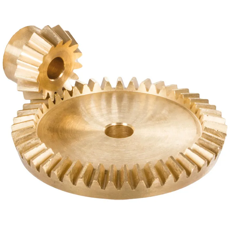
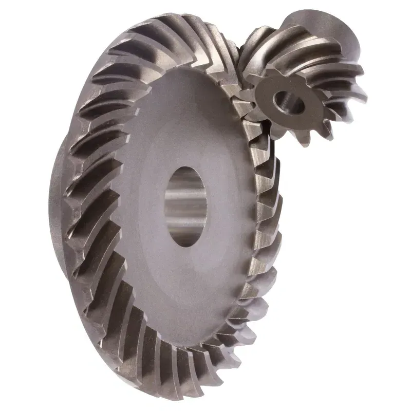
Steel Spiral Bevel Gears Ratio 3:1 Spiral Tooth System
Steel spiral bevel gears with a 3:1 ratio are conical gears designed to transmit power between intersecting shafts, typically at a 90-degree angle, with a speed reduction where the driven gear rotates at one-third the speed of the driving gear (pinion). The spiral tooth system features curved, oblique teeth, usually set at a 35-degree spiral angle, which ensures smoother engagement, reduced noise, and higher load-carrying capacity compared to straight bevel gears.
Steel spiral bevel gears with a 3:1 ratio are conical gears designed to transmit power between intersecting shafts, typically at a 90-degree angle, with a speed reduction where the driven gear rotates at one-third the speed of the driving gear (pinion). The spiral tooth system features curved, oblique teeth, usually set at a 35-degree spiral angle, which ensures smoother engagement, reduced noise, and higher load-carrying capacity compared to straight bevel gears.
Made from carbon or alloy steels, these spiral bevel gears are heat-treated for durability and are ideal for high-speed, heavy-duty applications like automotive differentials, industrial drives, and robotics. The 3:1 ratio is achieved by the driven gear having three times the number of teeth as the pinion, enhancing torque output. Their design requires precise manufacturing and matched sets for optimal performance, with robust bearings to handle axial thrust loads.
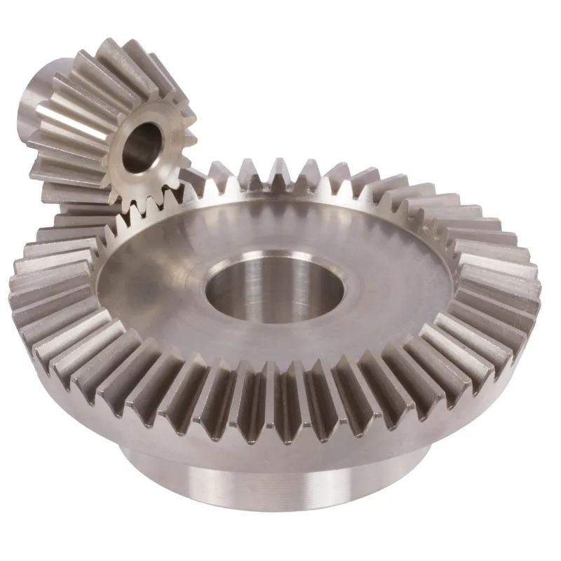
Steel Spiral Bevel Gear Ratio 3:1
| 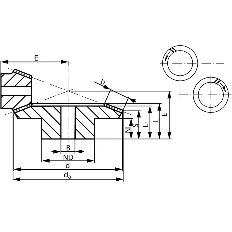 |
| Module | Number of teeth | da | d | ND | NL | L1 | L | S | b | BH7 | E | Torque* | Weight |
| mm | mm | mm | mm | mm | mm | mm | mm | mm | mm | Ncm | g | ||
| 0,6 | 20 | 19,1 | 18 | 15 | 7,5 | 17,7 | 17,7 | 8,2 | 10 | 6 | 35 | 2,1 | 175 |
| 0,6 | 60 | 54,3 | 54 | 45 | 8 | 16 | 19,7 | 16,6 | 10 | 10 | 25 | 6,3 | 175 |
| 1 | 16 | 26,1 | 24 | 20 | 8,3 | 22 | 22,6 | 9,3 | 14 | 8 | 45 | 5,8 | 380 |
| 1 | 48 | 72,5 | 72 | 50 | 8 | 18 | 21,3 | 16,8 | 14 | 12 | 28 | 17,4 | 380 |
| 1,3 | 11 | 25,1 | 22 | 19 | 6 | 17 | 17,9 | 7,5 | 11 | 8 | 40 | 7,7 | 320 |
| 1,3 | 33 | 66,6 | 60 | 40 | 8 | 17 | 20,4 | 16,9 | 11 | 12 | 27 | 23,1 | 320 |
| 1,5 | 10 | 26,0 | 22 | 17 | 8 | 19 | 20,1 | 9,6 | 11 | 8 | 42 | 9,1 | 380 |
| 1,5 | 30 | 66,6 | 66 | 40 | 8 | 17 | 21,3 | 17,8 | 11 | 12 | 28 | 27,3 | 380 |
| 2,2291 | 9 | 36,5 | 32 | 22 | 11 | 24 | 25,8 | 15,4 | 13 | 8 | 60,52 | 28 | 638 |
| 2,2291 | 27 | 96,0 | 96 | 48 | 19 | 25 | 29,5 | 25,5 | 13 | 20 | 40 | 84 | 638 |
| 2,5736 | 9 | 42,0 | 37,5 | 27 | 12 | 26,5 | 28,64 | 15,1 | 15 | 12 | 69,84 | 46 | 1100 |
| 2,5736 | 27 | 113,0 | 112,5 | 54 | 24 | 32 | 38,41 | 33,9 | 15 | 25 | 50 | 138 | 1100 |
| 3,5 | 9 | 59,0 | 52,5 | 40 | 12 | 33 | 36,2 | 18,9 | 22 | 16 | 92,64 | 132 | 2700 |
| 3,5 | 27 | 158,5 | 157,5 | 70 | 29 | 40 | 47,9 | 41,2 | 22 | 30 | 65 | 396 | 2700 |
Key Features of Steel Spiral Bevel Gears
- Spiral Tooth Design
Steel spiral bevel gears feature curved, oblique teeth set at a 35-degree angle. This design ensures gradual tooth engagement, reducing noise and vibration while improving load distribution, making them ideal for high-speed, high-torque applications like automotive differentials and industrial machinery. - 3:1 Gear Ratio
The 3:1 ratio means the driven gear has three times the teeth of the pinion, resulting in a one-third speed reduction and increased torque output. This configuration is critical for applications requiring precise speed control and enhanced power transmission in heavy-duty systems. - High-Strength Steel Construction
Made from carbon or alloy steels, these spiral bevel gears undergo heat treatment for superior hardness and durability. This ensures resistance to wear and fatigue, allowing them to handle high loads and harsh operating conditions in industries like manufacturing, aerospace, and automotive. - Efficient Power Transmission
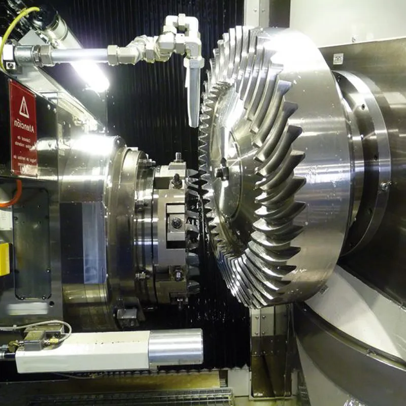
The spiral tooth system optimizes contact between gears, minimizing energy loss and improving efficiency. This design supports smooth operation under heavy loads, making these steel bevel gears suitable for demanding applications where reliable power transfer between intersecting shafts is essential. - Precision Manufacturing
Spiral bevel gears require advanced machining for accurate tooth geometry and alignment. This precision ensures proper meshing, reduces backlash, and enhances performance. Matched gear sets are critical to maintain efficiency and longevity in applications like robotics and heavy machinery. - Thrust Load Management
The spiral tooth configuration generates axial thrust, requiring robust bearing systems to support the gears. This design consideration ensures stability and longevity, particularly in high-speed applications where forces are significant, such as in marine propulsion or industrial gearboxes.
Steel Spiral Bevel Gear Uses
- Automotive Industry
Steel spiral bevel gears are widely used in automotive differentials to transfer torque between the driveshaft and wheels. Their smooth operation and ability to handle high loads ensure seamless power distribution, improving vehicle performance, stability, and overall driving experience under varying road conditions. - Aerospace Engineering
In aerospace applications, these gears play a critical role in flight control systems, actuators, and engine components. Their precise power transmission, lightweight design, and ability to withstand high stresses make them indispensable in meeting the stringent reliability and safety requirements of aircraft and spacecraft. - Industrial Machinery
Steel spiral bevel gears are essential in heavy-duty industrial equipment such as conveyors, milling machines, and robotic arms. Their durability, high torque transmission, and compact size make them ideal for applications requiring efficient and reliable motion transfer in harsh manufacturing environments. - Power Generation Equipment
These gears are used in turbines, wind generators, and hydroelectric systems, where efficient energy transfer is crucial. Their robust construction and ability to handle high-speed operations ensure consistent performance, enabling the efficient conversion of mechanical energy into electrical power in renewable energy systems. - Marine and Offshore Engineering
In marine propulsion systems, steel bevel gears facilitate motion transfer between engines and propellers. Their corrosion-resistant properties and ability to manage high torque loads under extreme conditions make them suitable for use in ships, submarines, and offshore drilling platforms. - Mining and Construction Equipment
Steel spiral bevel gears are utilized in heavy machinery like excavators, loaders, and crushers in the mining and construction industries. Their ability to handle extreme loads, resist wear, and operate reliably in dusty, high-impact environments ensures efficient performance in demanding applications.
 |  |
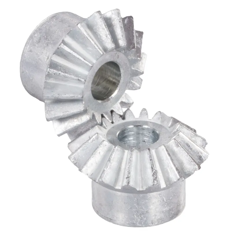
| Bevel Gear for Automotive Industry | Bevel Gear for Robotics |
 |  |
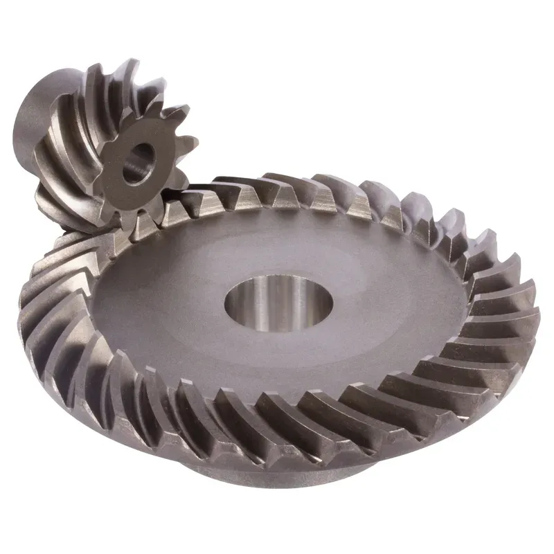
| Bevel Gear for Industrial Machinery | Bevel Gear for Marine Industry |
Steel Spiral Bevel Gear Troubleshooting
- Excessive Noise During Operation
If the gear produces excessive noise, it may result from improper alignment, insufficient lubrication, or worn teeth. Carefully inspect the alignment of the gears, ensure proper lubrication is applied, and check for damage or uneven wear on the gear teeth. - Vibration or Unstable Performance
Unusual vibrations can occur due to loose mounting, misalignment, or imbalanced load distribution. Verify that the gears are securely mounted, adjust the alignment to the correct specifications, and ensure the load is evenly distributed across the gear teeth to prevent instability. - Premature Tooth Wear
If the gear teeth wear down faster than expected, it may be caused by inadequate lubrication, excessive loads, or poor-quality materials. Check the lubrication system for proper functioning, ensure the gear is not overloaded, and confirm that high-grade steel is used. - Overheating During Operation
Overheating can result from insufficient lubrication, excessive friction, or overloading. Inspect the lubrication system for blockages or leaks, reduce the load if it exceeds the gear’s capacity, and ensure the operating environment allows proper heat dissipation for the gear system. - Tooth Chipping or Breakage
Chipping or breaking of gear teeth often occurs due to sudden impact loads, material fatigue, or manufacturing defects. Regularly inspect the gears for signs of fatigue, avoid subjecting the system to shock loads, and ensure the gears meet quality standards during production. - Misalignment Issues
Misalignment between the driving and driven gears can cause uneven wear, noise, and performance inefficiency. Check the installation for proper alignment, adjust the positioning as needed, and use precision tools during installation to ensure the gears operate at optimal alignment angles.
Additional information
| Edited by | Yjx |
|---|