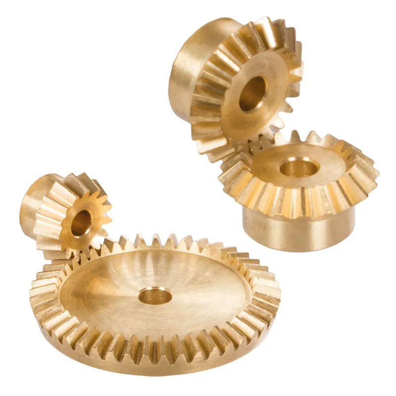
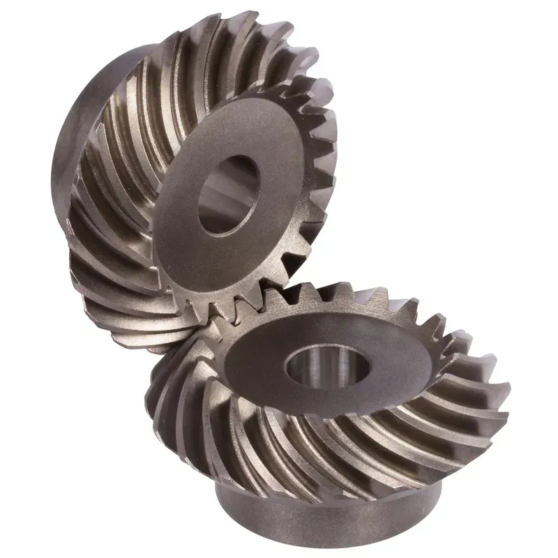
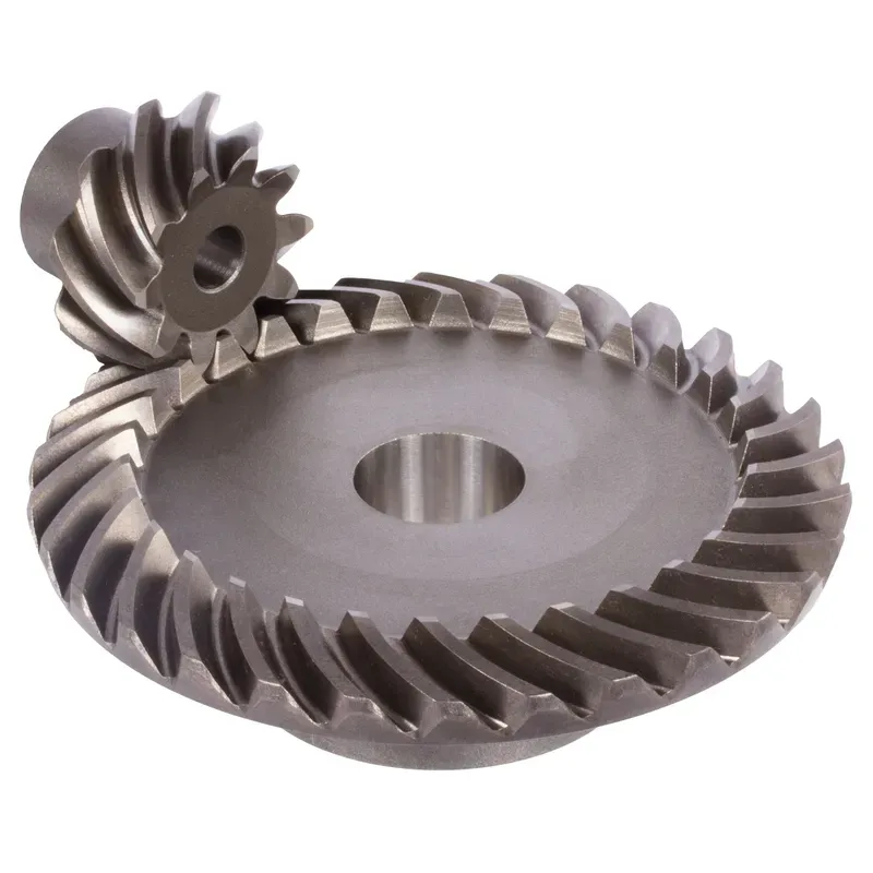
Steel Spiral Bevel Gears Ratio 1:1 – 4:1 Spiral Tooth System
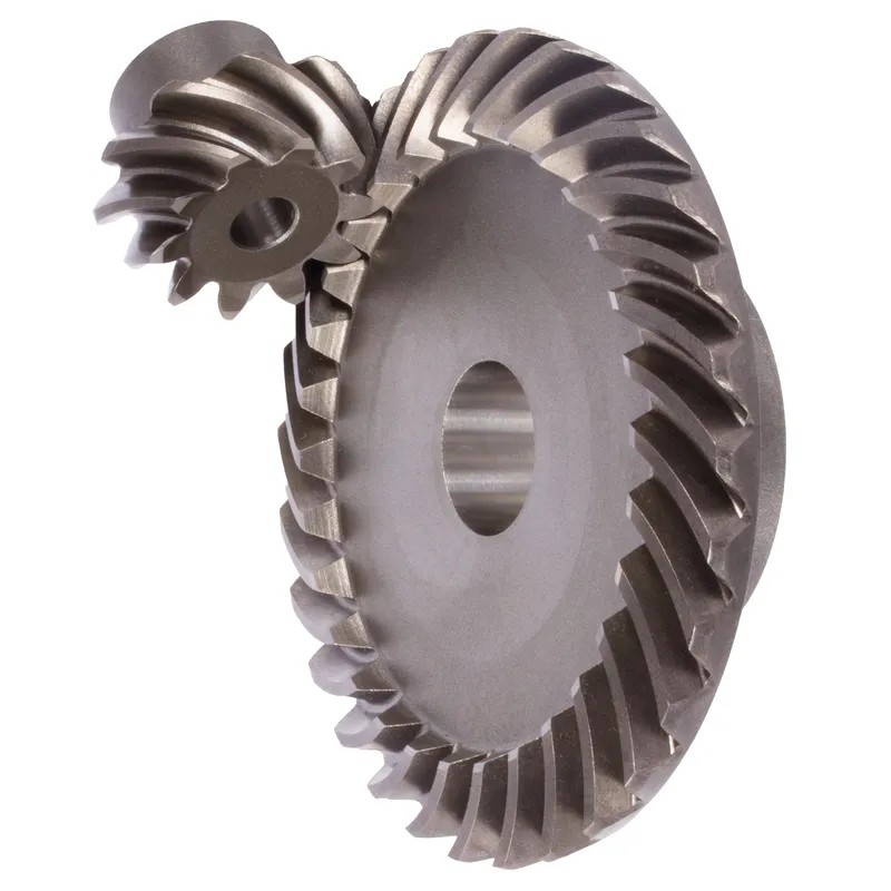
Steel spiral bevel gears with a ratio of 1.2:1 to 1.6:1 and a spiral tooth system are conical gears designed to transmit power between intersecting shafts, typically at a 90-degree angle. The spiral tooth design, with curved and angled teeth (often 35° spiral angle), ensures smoother and quieter operation compared to straight bevel gears due to gradual tooth engagement and higher contact ratios. These steel bevel gears are made from high-strength carbon or alloy steels like 42CrMo4 or 16MnCr5, suitable for moderate speed reductions in applications like automotive differentials or industrial machinery.
Steel spiral bevel gears with a ratio of 1:1 to 4:1 and a spiral tooth system are conical gears designed to transmit power between intersecting shafts, typically at a 90-degree angle. The spiral tooth design, with curved and angled teeth (often 35° spiral angle), ensures smoother and quieter operation compared to straight bevel gears due to gradual tooth engagement and higher contact ratios. These gears are made from high-strength carbon or alloy steels like 42CrMo4 (for modules up to 1.5) or 16MnCr5 (for modules 2.0 and above), with hardened teeth for durability. The gear ratio, calculated as the number of teeth on the driven gear divided by the pinion, ranges from 1:1 to 4:1, making them suitable for moderate speed reductions in applications like automotive differentials or industrial machinery.
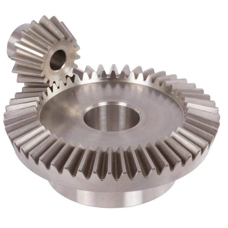
Steel Spiral Bevel Gear Ratio 1:1
 | 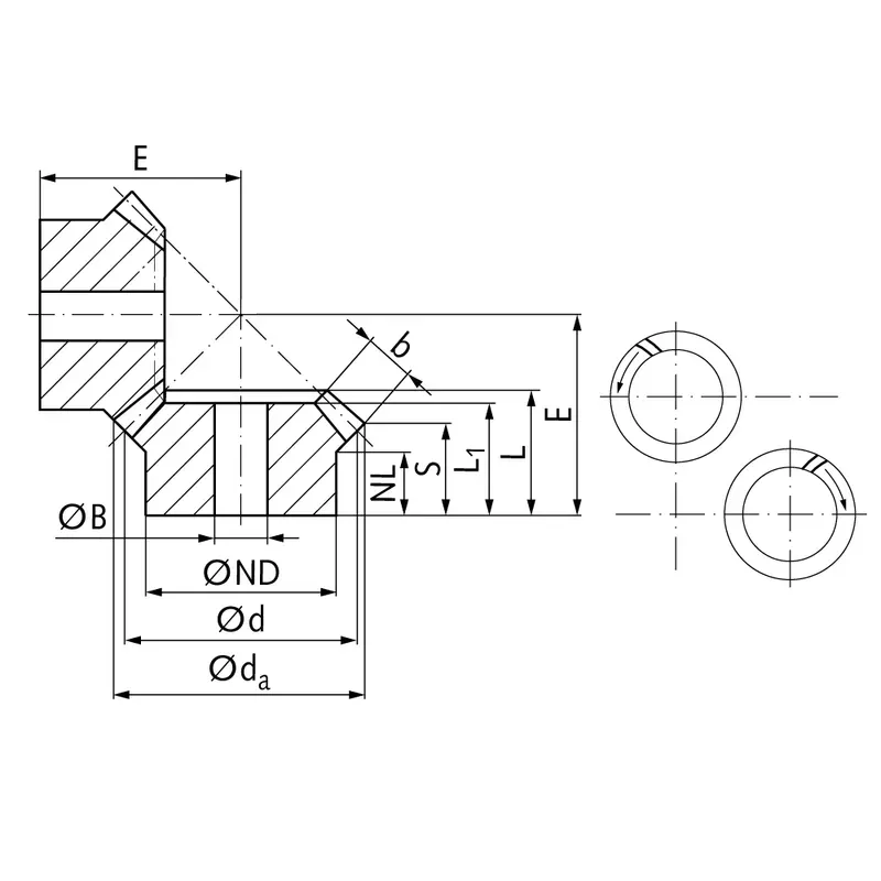 |
| Module | Number of teeth | da | d | ND | NL | L1 | L | S1) | b | BH7 | E | Torque* | Weight |
| mm | mm | mm | mm | mm | mm | mm | mm | mm | mm | Ncm | g | ||
| 0,6 | 16 | 15,8 | 15,5 | 10 | 4,5 | 9 | 10,0 | 7,7 | 3,3 | 5 | 15 | 0,64 | 12 |
| 0,6 | 20 | 16,9 | 16,5 | 12 | 6,5 | 11 | 12,0 | 9,2 | 4 | 5 | 17 | 1,27 | 19 |
| 0,6 | 25 | 23,3 | 22,5 | 19 | 7,2 | 12 | 13,4 | 9,2 | 6 | 6 | 20 | 2,1 | 50 |
| 0,6 | 30 | 27,8 | 27 | 22 | 7 | 13 | 14,9 | 9,9 | 7 | 8 | 23 | 3,0 | 75 |
| 0,6 | 35 | 32,3 | 31,5 | 25 | 7,2 | 15 | 16,3 | 10,6 | 8 | 8 | 26 | 3,5 | 116 |
| 1 | 16 | 25,4 | 24 | 17 | 7,5 | 13,5 | 15,95 | 11,7 | 6 | 6 | 23 | 2,5 | 55 |
| 1 | 20 | 31,4 | 30 | 25 | 8,4 | 15 | 17,3 | 11,7 | 8 | 8 | 26 | 6,3 | 112 |
| 1 | 25 | 38,9 | 37,5 | 25 | 8 | 16 | 19,0 | 11,9 | 10 | 10 | 30 | 10,0 | 155 |
| 1 | 30 | 46,4 | 45 | 30 | 8 | 19 | 21,7 | 13,2 | 12 | 10 | 35 | 14,3 | 278 |
| 1,3 | 20 | 41,8 | 40 | 30 | 7,3 | 19 | 20,7 | 12,9 | 11 | 10 | 32 | 14,8 | 222 |
| 1,3 | 25 | 51,8 | 50 | 30 | 8 | 19 | 21,8 | 11,9 | 14 | 10 | 36 | 18,5 | 326 |
| 1,3 | 30 | 61,8 | 60 | 35 | 8 | 21 | 24,2 | 12,9 | 16 | 12 | 42 | 31,5 | 530 |
| 1,5 | 18 | 41,7 | 39,6 | 30 | 8 | 17 | 20,3 | 13,2 | 10 | 10 | 32 | 15,9 | 209 |
| 1,5 | 24 | 54,9 | 52,8 | 35 | 8 | 20 | 22,6 | 12,7 | 14 | 10 | 38 | 21,2 | 408 |
| 1,5 | 28 | 63,7 | 61,6 | 40 | 8 | 20 | 23,2 | 13,3 | 14 | 12 | 43 | 34,5 | 576 |
| 2,2881 | 21 | 71,5 | 70 | 45 | 15 | 28 | 32,22 | 22,5 | 15 | 16 | 55 | 70 | 973 |
| 2,236 | 24 | 79,0 | 78 | 45 | 15 | 29 | 32,48 | 23,7 | 14 | 16 | 60 | 73 | 1200 |
| 2 | 26 | 82,0 | 80 | 55 | 20 | 35 | 37,73 | 26,8 | 16 | 16 | 65 | 42 | 1581 |
| 2,5 | 19 | 90,0 | 88 | 56 | 18 | 34 | 36,91 | 23,5 | 20 | 20 | 65 | 185 | 1700 |
| 2,5 | 24 | 98,0 | 96 | 54 | 16 | 32 | 37,2 | 24,5 | 19 | 20 | 70 | 188 | 2000 |
| 3 | 21 | 103,0 | 100 | 68 | 17 | 36 | 43,4 | 27,7 | 23 | 25 | 75 | 240 | 2600 |
| 3 | 24 | 115,0 | 112 | 64 | 18 | 34 | 41,7 | 26,7 | 22 | 25 | 80 | 260 | 2800 |
| 3,5 | 24 | 131,0 | 128 | 72 | 20 | 38 | 46,15 | 29,5 | 25 | 30 | 90 | 396 | 4200 |
| 3,5 | 26 | 144,0 | 140 | 85 | 30 | 57 | 62,3 | 43,0 | 28 | 30 | 110 | 238 | 7300 |
Steel Spiral Bevel Gear Ratio 1.214:1
|  |
| Module | Number of teeth | da | d | ND | NL | L1 | L | S | b | BH7 | E | Torque* | Weight |
| mm | mm | mm | mm | mm | mm | mm | mm | mm | mm | Ncm | g | ||
| 1,5 | 14 | 41,0 | 38,7 | 22 | 11 | 21,1 | 24,3 | 15,4 | 11,5 | 12 | 38,0 | 14,1 | 236 |
| 1,5 | 17 | 48,9 | 47,0 | 30 | 11 | 20,9 | 23,9 | 16,6 | 11,5 | 15 | 34,8 | 17,1 | 236 |
Steel Spiral Bevel Gear Ratio 1.385:1
| |
| Module | Number of teeth | da | d | ND | NL | L1 | L | S | b | BH7 | E | Torque* | Weight |
| mm | mm | mm | mm | mm | mm | mm | mm | mm | mm | Ncm | g | ||
| 1,5 | 13 | 36,7 | 33,9 | 22 | 11 | 21,6 | 24,1 | 16,0 | 10 | 12 | 38,5 | 11,3 | 216 |
| 1,5 | 18 | 48,5 | 47,0 | 30 | 11 | 20,9 | 24,7 | 18,9 | 10 | 15 | 34,8 | 15,7 | 216 |
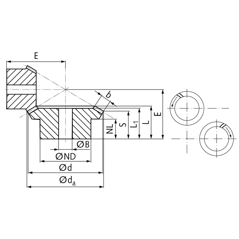
Steel Spiral Bevel Gear Ratio 1.5:1
| |
| Module | Number of teeth | da | d | ND | NL | L1 | L | S | b | BH7 | E | Torque* | Weight |
| mm | mm | mm | mm | mm | mm | mm | mm | mm | mm | Ncm | g | ||
| 0,6 | 22 | 20,8 | 19,8 | 17 | 7 | 13 | 14,3 | 8,5 | 7 | 6 | 23 | 2,2 | 116 |
| 0,6 | 33 | 30,3 | 29,7 | 20 | 8 | 14 | 15,5 | 11,6 | 7 | 8 | 21 | 3,3 | 116 |
| 1 | 20 | 31,6 | 30 | 25 | 8 | 17 | 18,3 | 10,0 | 10 | 8 | 32 | 8,1 | 166 |
| 1 | 30 | 46,3 | 45 | 30 | 8 | 17 | 19,5 | 14,0 | 10 | 10 | 28 | 12,2 | 166 |
| 1,3 | 16 | 34,3 | 32 | 25 | 8 | 18 | 19,9 | 10,7 | 11 | 8 | 34 | 11,9 | 220 |
| 1,3 | 24 | 49,4 | 48 | 30 | 8 | 18 | 21,1 | 15,0 | 11 | 10 | 30 | 17,9 | 220 |
| 1,5 | 16 | 37,8 | 35,8 | 30 | 8 | 17 | 18,8 | 10,5 | 10 | 10 | 36 | 14,3 | 273 |
| 1,5 | 24 | 54,4 | 52,8 | 35 | 8 | 17 | 21,1 | 15,6 | 10 | 10 | 32 | 21,5 | 273 |
| 2 | 16 | 53,0 | 50 | 35 | 6 | 18 | 21,37 | 12,8 | 11 | 10 | 48,45 | 41,0 | 561 |
| 2 | 24 | 76,0 | 75 | 39 | 15 | 24 | 27,53 | 21,7 | 11 | 16 | 45 | 61,5 | 561 |
| 2,5 | 16 | 67,0 | 64 | 40 | 14 | 25 | 31,89 | 19,9 | 16 | 16 | 65 | 84 | 1300 |
| 2,5 | 24 | 97,5 | 96 | 54 | 14 | 23 | 28,66 | 20,1 | 16 | 20 | 50 | 126 | 1300 |
| 3 | 16 | 79,0 | 76 | 50 | 15 | 28 | 35,71 | 21,9 | 19 | 20 | 75 | 160 | 1682 |
| 3 | 24 | 115,0 | 114 | 64 | 18 | 28 | 34,69 | 24,8 | 19 | 25 | 60 | 240 | 1682 |
Steel Spiral Bevel Gear Ratio 1.615:1
| |
| Module | Number of teeth | da | d | ND | NL | L1 | L | S | b | BH7 | E | Torque* | Weight |
| mm | mm | mm | mm | mm | mm | mm | mm | mm | mm | Ncm | g | ||
| 1 | 13 | 20,8 | 18,6 | 16 | 8,2 | 12 | 13,9 | 9,3 | 5 | 8 | 24 | 2,4 | 45 |
| 1 | 21 | 30,8 | 30,0 | 20 | 6 | 10,5 | 12,0 | 9,3 | 5 | 10 | 18 | 3,9 | 45 |
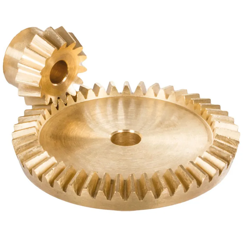
Steel Spiral Bevel Gear Ratio 2:1
 | 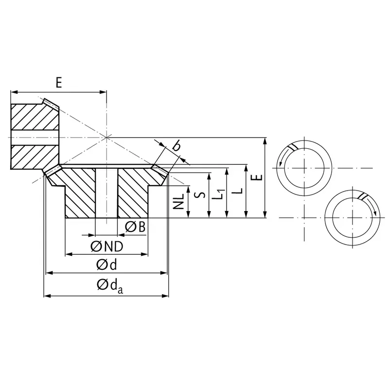 |
| Module | Number of teeth | da | d | ND | NL | L1 | L | S | b | BH7 | E | Torque* | Weight |
| mm | mm | mm | mm | mm | mm | mm | mm | mm | mm | Ncm | g | ||
| 0,6 | 22 | 20,8 | 19,8 | 16 | 7,4 | 15 | 15,6 | 8,5 | 8 | 6 | 28 | 2,3 | 116 |
| 0,6 | 44 | 40,1 | 39,6 | 25 | 8 | 15 | 17,2 | 13,6 | 8 | 10 | 23 | 4,6 | 116 |
| 1 | 20 | 31,8 | 30 | 25 | 8 | 19 | 20,2 | 9,4 | 12 | 8 | 39 | 9,8 | 323 |
| 1 | 40 | 60,9 | 60 | 40 | 8 | 18 | 21,2 | 15,9 | 12 | 12 | 30 | 19,6 | 323 |
| 1,3 | 16 | 34,4 | 32 | 25 | 7 | 20 | 22,1 | 9,6 | 14 | 8 | 41 | 12,0 | 397 |
| 1,3 | 32 | 65,1 | 64 | 40 | 8 | 20 | 23,3 | 17,1 | 14 | 12 | 32 | 24,0 | 397 |
| 1,5 | 16 | 38,0 | 35,2 | 30 | 8,4 | 19 | 21,2 | 10,5 | 12 | 10 | 45 | 14,4 | 435 |
| 1,5 | 32 | 71,7 | 70,4 | 45 | 8 | 17 | 21,0 | 15,7 | 12 | 12 | 32 | 28,8 | 435 |
| 2,269 | 12 | 44,0 | 41,5 | 30 | 12 | 28,23 | 28,23 | 17,6 | 15 | 12 | 55 | 10,1 | 846 |
| 2,269 | 24 | 83,0 | 83 | 50 | 15 | 27 | 32,41 | 26,0 | 15 | 16 | 45 | 20,2 | 846 |
| 2,321 | 13 | 47,0 | 45 | 30 | 15 | 30 | 33,0 | 21,7 | 15 | 10 | 63,65 | 49 | 818 |
| 2,321 | 26 | 91,0 | 90 | 40 | 22 | 30 | 35,5 | 29,8 | 15 | 16 | 50 | 98 | 818 |
| 2,5 | 11 | 57,0 | 52,5 | 40 | 15 | 36,72 | 36,72 | 19,7 | 20 | 16 | 70 | 17,8 | 2000 |
| 2,5 | 22 | 106,0 | 105 | 70 | 20 | 39 | 44,65 | 35,8 | 20 | 20 | 60 | 35,6 | 2000 |
| 2,5 | 13 | 59,0 | 56 | 39 | 15 | 34 | 38,37 | 22,9 | 20 | 16 | 75,13 | 95 | 1400 |
| 2,5 | 26 | 113,0 | 112 | 54 | 21 | 30 | 37,72 | 29,0 | 20 | 25 | 55 | 190 | 1400 |
| 3 | 13 | 68,0 | 64 | 45 | 16 | 37 | 41,95 | 24,9 | 22 | 20 | 84,62 | 133 | 2000 |
| 3 | 26 | 128,0 | 128 | 54 | 20 | 32 | 39,9 | 30,6 | 22 | 25 | 60 | 266 | 2000 |
| 3 | 14 | 76,0 | 72,5 | 55 | 25 | 51,46 | 51,46 | 32,0 | 25 | 20 | 100 | 644 | 4800 |
| 3 | 28 | 146,0 | 145 | 90 | 25 | 50 | 57,1 | 46,2 | 25 | 30 | 80 | 128 | 4800 |
| 3,5 | 13 | 77,0 | 72 | 54 | 12 | 34 | 39,8 | 21,1 | 24 | 20 | 88,38 | 197 | 2800 |
| 3,5 | 26 | 146,0 | 144 | 64 | 25 | 38 | 47,1 | 36,5 | 24 | 30 | 70 | 394 | 2800 |
Steel Spiral Bevel Gear Ratio 2.066:1
| |
| Module | Number of teeth | da | d | ND | NL | L1 | L | S | b | BH7 | E | Torque* | Weight |
| mm | mm | mm | mm | mm | mm | mm | mm | mm | mm | Ncm | g | ||
| 1 | 15 | 24,1 | 21,8 | 19 | 6 | 13,2 | 13,3 | 7,0 | 7 | 8 | 29,0 | 3,6 | 112 |
| 1 | 31 | 45,6 | 45,0 | 24 | 8 | 14,0 | 16,3 | 13,2 | 7 | 10 | 23,5 | 7,4 | 112 |
Steel Spiral Bevel Gear Ratio 2.5:1
| |
| Module | Number of teeth | da | d | ND | NL | L1 | L | S | b | BH7 | E | Torque* | Weight |
| mm | mm | mm | mm | mm | mm | mm | mm | mm | mm | Ncm | g | ||
| 0,6 | 22 | 20,9 | 19,8 | 16 | 6,8 | 16 | 16,7 | 7,5 | 10 | 6 | 32 | 2,6 | 172 |
| 0,6 | 55 | 49,9 | 49,5 | 30 | 8 | 16 | 19,3 | 15,6 | 10 | 10 | 25 | 6,5 | 172 |
| 1,0 | 20 | 31,8 | 30 | 25 | 8,4 | 21 | 22,8 | 9,8 | 14 | 8 | 47 | 9,9 | 355 |
| 1,0 | 50 | 75,7 | 75 | 50 | 8 | 18 | 21,1 | 15,9 | 14 | 12 | 30 | 24,8 | 355 |
| 1,3 | 14 | 30,5 | 28 | 22 | 8,7 | 20 | 21,6 | 10,5 | 12 | 8 | 45 | 11,3 | 420 |
| 1,3 | 35 | 70,9 | 70 | 45 | 8 | 18 | 21,6 | 17,1 | 12 | 12 | 30 | 28,2 | 420 |
| 1,5 | 16 | 38,0 | 35,2 | 30 | 7,5 | 20 | 21,6 | 9,6 | 13 | 10 | 53 | 14,5 | 624 |
| 1,5 | 40 | 89,1 | 88 | 60 | 8 | 16 | 20,6 | 15,8 | 13 | 15 | 32 | 36,3 | 624 |
| 3,6 | 9 | 62,0 | 54,78 | 40 | 14,17 | 34 | 38,35 | 20,9 | 21 | 16 | 87,06 | 150 | 2400 |
| 3,6 | 23 | 141,0 | 140 | 70 | 35 | 45 | 52,53 | 45,0 | 21 | 30 | 70 | 383 | 2400 |
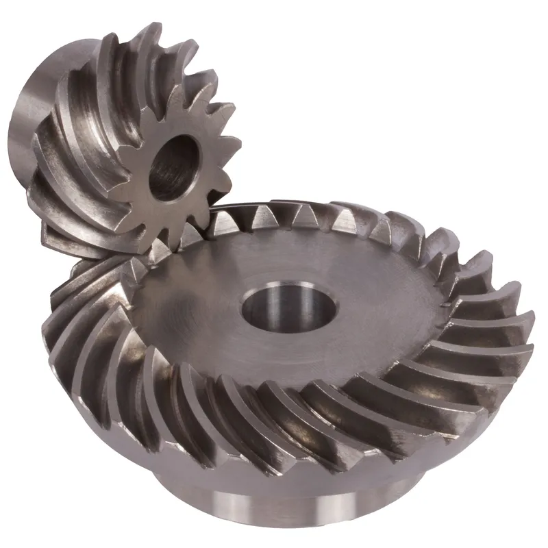
Steel Spiral Bevel Gear Ratio 3:1
 |  |
| Module | Number of teeth | da | d | ND | NL | L1 | L | S | b | BH7 | E | Torque* | Weight |
| mm | mm | mm | mm | mm | mm | mm | mm | mm | mm | Ncm | g | ||
| 0,6 | 20 | 19,1 | 18 | 15 | 7,5 | 17,7 | 17,7 | 8,2 | 10 | 6 | 35 | 2,1 | 175 |
| 0,6 | 60 | 54,3 | 54 | 45 | 8 | 16 | 19,7 | 16,6 | 10 | 10 | 25 | 6,3 | 175 |
| 1 | 16 | 26,1 | 24 | 20 | 8,3 | 22 | 22,6 | 9,3 | 14 | 8 | 45 | 5,8 | 380 |
| 1 | 48 | 72,5 | 72 | 50 | 8 | 18 | 21,3 | 16,8 | 14 | 12 | 28 | 17,4 | 380 |
| 1,3 | 11 | 25,1 | 22 | 19 | 6 | 17 | 17,9 | 7,5 | 11 | 8 | 40 | 7,7 | 320 |
| 1,3 | 33 | 66,6 | 60 | 40 | 8 | 17 | 20,4 | 16,9 | 11 | 12 | 27 | 23,1 | 320 |
| 1,5 | 10 | 26,0 | 22 | 17 | 8 | 19 | 20,1 | 9,6 | 11 | 8 | 42 | 9,1 | 380 |
| 1,5 | 30 | 66,6 | 66 | 40 | 8 | 17 | 21,3 | 17,8 | 11 | 12 | 28 | 27,3 | 380 |
| 2,2291 | 9 | 36,5 | 32 | 22 | 11 | 24 | 25,8 | 15,4 | 13 | 8 | 60,52 | 28 | 638 |
| 2,2291 | 27 | 96,0 | 96 | 48 | 19 | 25 | 29,5 | 25,5 | 13 | 20 | 40 | 84 | 638 |
| 2,5736 | 9 | 42,0 | 37,5 | 27 | 12 | 26,5 | 28,64 | 15,1 | 15 | 12 | 69,84 | 46 | 1100 |
| 2,5736 | 27 | 113,0 | 112,5 | 54 | 24 | 32 | 38,41 | 33,9 | 15 | 25 | 50 | 138 | 1100 |
| 3,5 | 9 | 59,0 | 52,5 | 40 | 12 | 33 | 36,2 | 18,9 | 22 | 16 | 92,64 | 132 | 2700 |
| 3,5 | 27 | 158,5 | 157,5 | 70 | 29 | 40 | 47,9 | 41,2 | 22 | 30 | 65 | 396 | 2700 |
Steel Spiral Bevel Gear Ratio 4:1
| |
| Module | Number of teeth | da | d | ND | NL | L1 | L | S | b | BH7 | E | Torque* | Weight |
| mm | mm | mm | mm | mm | mm | mm | mm | mm | mm | Ncm | g | ||
| 1 | 16 | 25,9 | 24 | 20 | 7,3 | 21 | 21,8 | 8,2 | 14 | 8 | 56 | 7,8 | 842 |
| 1 | 64 | 96,5 | 96 | 70 | 8 | 19 | 22,4 | 19 | 14 | 20 | 30 | 31,2 | 842 |
| 1,5 | 11 | 27,8 | 24,2 | 20 | 8 | 19 | 20,7 | 9 | 12 | 8 | 57 | 11,3 | 775 |
| 1,5 | 44 | 97,3 | 96,8 | 70 | 8 | 17 | 21,9 | 19 | 12 | 20 | 30 | 45,2 | 775 |
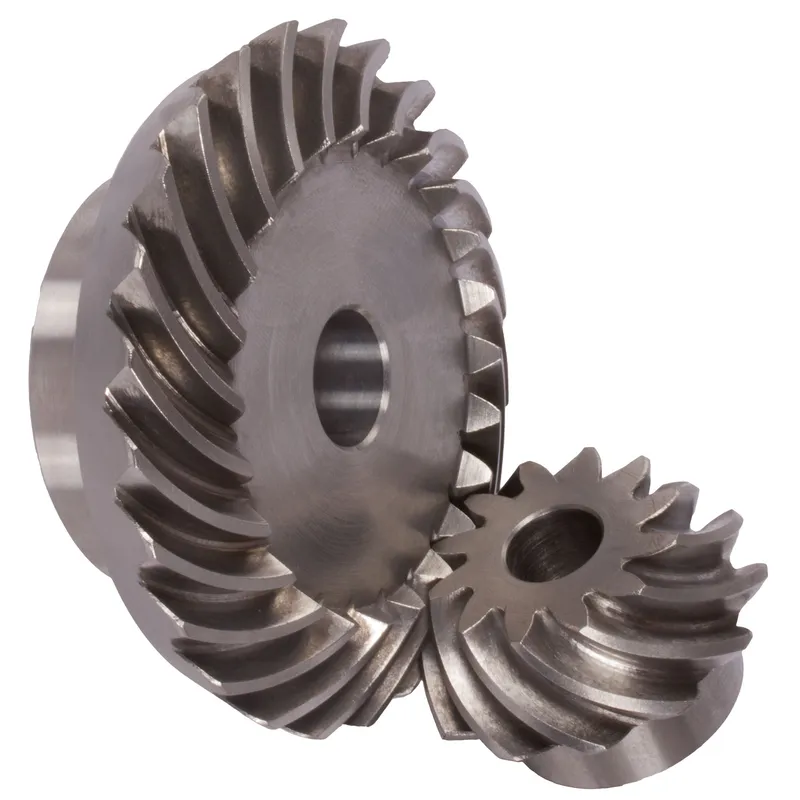
Advantages of Steel Spiral Bevel Gears
1. High Torque Capacity
One of the key advantages of bevel gears is their ability to handle high torque loads. The geometry and design of bevel gears allow for efficient transmission of power and torque between intersecting shafts.
2. Compact Design
Bevel gears offer a compact solution for power transmission between non-parallel shafts. By utilizing a conical geometry, bevel gears can effectively change the direction of rotation within a limited space.
3. Smooth and Quiet Operation
When properly designed and manufactured, bevel gears can provide smooth and quiet operation. Advancements in gear tooth geometry, such as the use of spiral bevel gears and hypoid gears, have significantly improved the smoothness and noise reduction capabilities of bevel gears. The curved teeth profile of spiral bevel gears allows for gradual engagement and disengagement, resulting in quieter operation compared to straight bevel gears.
4. Versatility in Shaft Angles
Bevel gears offer flexibility in terms of the shaft angles they can accommodate. While the most common shaft angle for bevel gears is 90 degrees, they can be designed to work with various shaft angles.
Disadvantages of Steel Spiral Bevel Gears
1. Higher Manufacturing Complexity
One of the main disadvantages of bevel gears is their higher manufacturing complexity compared to other gear types, such as spur gears. The production of bevel gears requires specialized machinery and precise manufacturing processes to achieve the desired tooth geometry and surface finish. This complexity can result in increased manufacturing costs and longer lead times.
2. Sensitivity to Misalignment
Bevel gears are more sensitive to misalignment compared to other gear types. Misalignment can lead to uneven load distribution, increased stress on gear teeth, and premature failure.
3. Limited Speed Capability
Bevel gears have limitations in terms of their speed capability. At high speeds, bevel gears are prone to generating excessive noise and vibration due to the sliding action between the gear teeth. This can lead to reduced efficiency and increased wear. As a result, bevel gears are typically used in applications with moderate to low speed requirements.
4. Higher Cost
The manufacturing complexity and precision required for bevel gears often translate to higher costs compared to simpler gear types. The need for specialized machinery, skilled labor, and stringent quality control measures contributes to the increased cost of bevel gears. Additionally, the customization and specific design requirements of bevel gears for particular applications can further increase their cost.
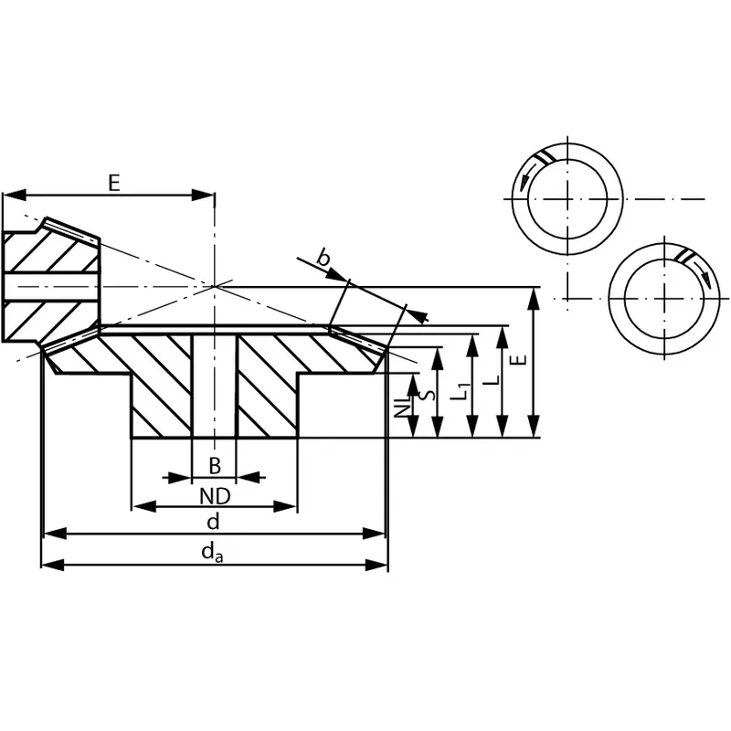
Key Dimensions & Angles of Bevel Gears
Bevel gears are complex mechanical components characterized by a range of critical dimensions and angles.
A. Detailed Examination of Basic Dimensions
Several key dimensions define the overall geometry and size of a bevel gear:
- Pitch Diameter: This diameter is measured at the heel end of the bevel gear teeth. It represents the effective size of the gear and is a fundamental parameter for gear calculations and design.
- Pitch Cone Angle: The pitch cone angle describes the angle formed by the pitch cone relative to the gear axis. It defines the orientation of the gear teeth and determines how the gear meshes with its mating pinion.
- Addendum & Dedendum: The addendum is the height of the gear tooth above the pitch cone, while the dedendum is the depth below it. Together, they define the total tooth depth. The addendum and dedendum are typically specified in proportion to the gear module.
- Face Width: Face width refers to the size of the gear tooth measured along the pitch cone generatrix from the heel to the toe. It affects gear tooth strength and load capacity. Wider face widths generally allow greater torque transmission.
- Cone Distance: The cone distance represents the length from the apex of the pitch cone to the mid-face of the bevel gear. It is a key dimension for positioning the gear relative to its mating pinion during assembly.
- Vertex Distance: Vertex distance measures the offset from the gear axis to the pitch cone apex. It helps locate the theoretical point of mesh between gears.
B. Essential Bevel Gear Angles
In addition to linear dimensions, several angles are critical in defining a bevel gear’s geometry:
- Face Angle: The angle between the face cone generatrix and the gear axis. It determines the angle of the outer ends of the gear teeth relative to the rotational axis.
- Edge Angle: Measured between the outer cone generatrix and gear axis, the edge angle defines the slope of the inner ends of the teeth nearest the apex.
- Addendum Angle: This is the angular equivalent of the addendum, defining the tooth height in angular terms from the face angle to the outside edge.
- Dedendum Angle: Correspondingly, the dedendum angle measures the angular tooth depth from the pitch line down to the tooth root.
C. Backlash
Backlash refers to the clearance or play between the teeth of two meshing gears. Some backlash is necessary to accommodate lubrication, manufacturing tolerances, and thermal expansion. However, excessive backlash can cause noise, vibration, and imprecise positioning. Backlash is typically measured at the tightest point of mesh using dedicated tools or by assessing the angular play with the gears held fixed.
D. Module
The module of a gear is a standardized unit that indicates tooth size. It is defined as the ratio of the pitch diameter to the number of teeth. In bevel gears, the module is typically specified at the heel end for manufacturing purposes. Larger module numbers correspond to bigger, coarser teeth, while finer pitch gears have smaller modules.
Additional information
| Edited by | Yjx |
|---|