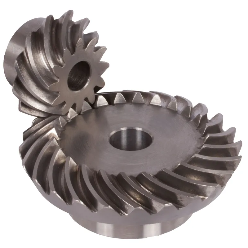
Steel Spiral Bevel Gears Ratio 1.385:1 Spiral Tooth System
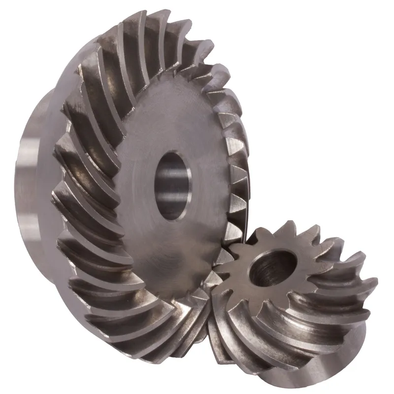
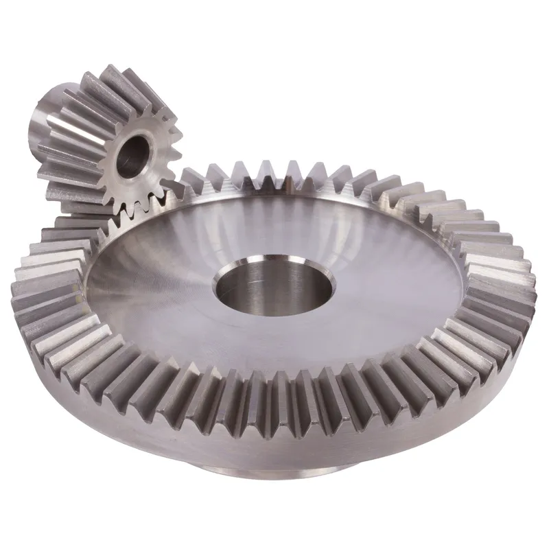
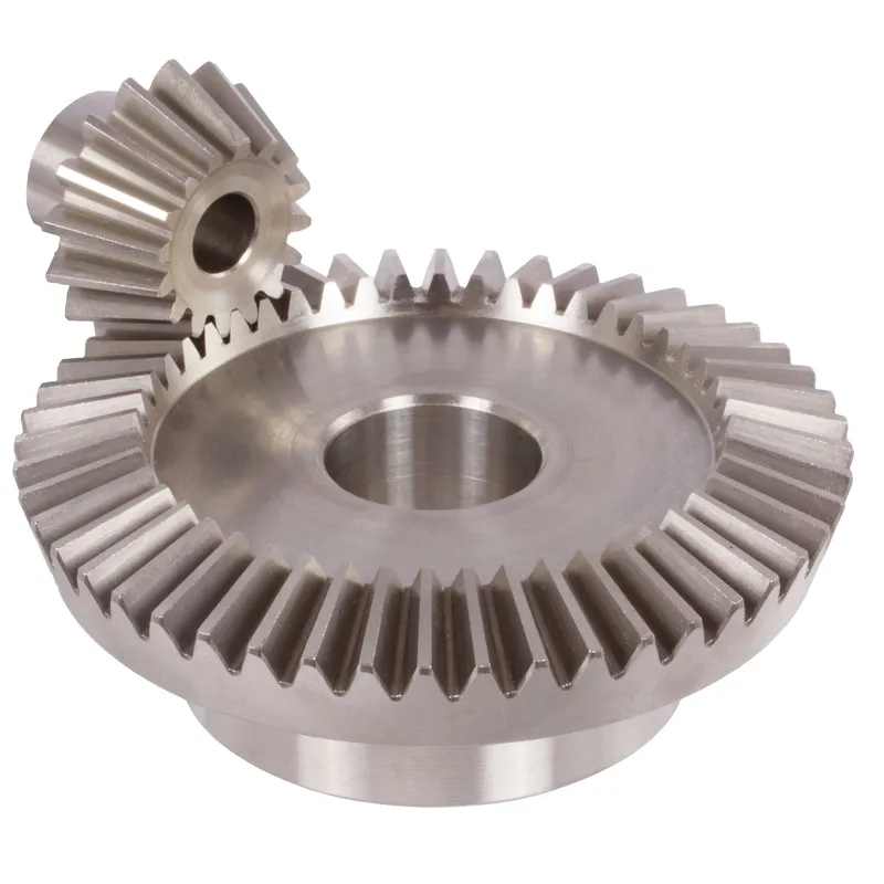
A steel spiral bevel gear with a 1.385:1 ratio and spiral tooth system is a specialized gear designed for transmitting rotational power between intersecting shafts, typically at a 90-degree angle, with high efficiency and strength. The spiral tooth system features curved, helical teeth (often with a 35° spiral angle) that engage gradually, reducing noise, vibration, and impact stress compared to straight bevel gears. This makes them ideal for high-speed, high-torque applications like industrial machinery, automotive differentials, and marine systems.
A steel spiral bevel gear with a 1.385:1 ratio and spiral tooth system is a specialized gear designed for transmitting rotational power between intersecting shafts, typically at a 90-degree angle, with high efficiency and strength. The spiral tooth system features curved, helical teeth (often with a 35° spiral angle) that engage gradually, reducing noise, vibration, and impact stress compared to straight bevel gears. This makes them ideal for high-speed, high-torque applications like industrial machinery, automotive differentials, and marine systems.
The 1.385:1 ratio indicates the pinion has fewer teeth than the gear, providing a slight speed reduction and torque increase. Typically made from hardened steel (e.g., 42CrMo4), these spiral bevel gears offer durability and are precision-manufactured for smooth operation and minimal backlash.
Steel Spiral Bevel Gear Ratio 1.385:1
 | 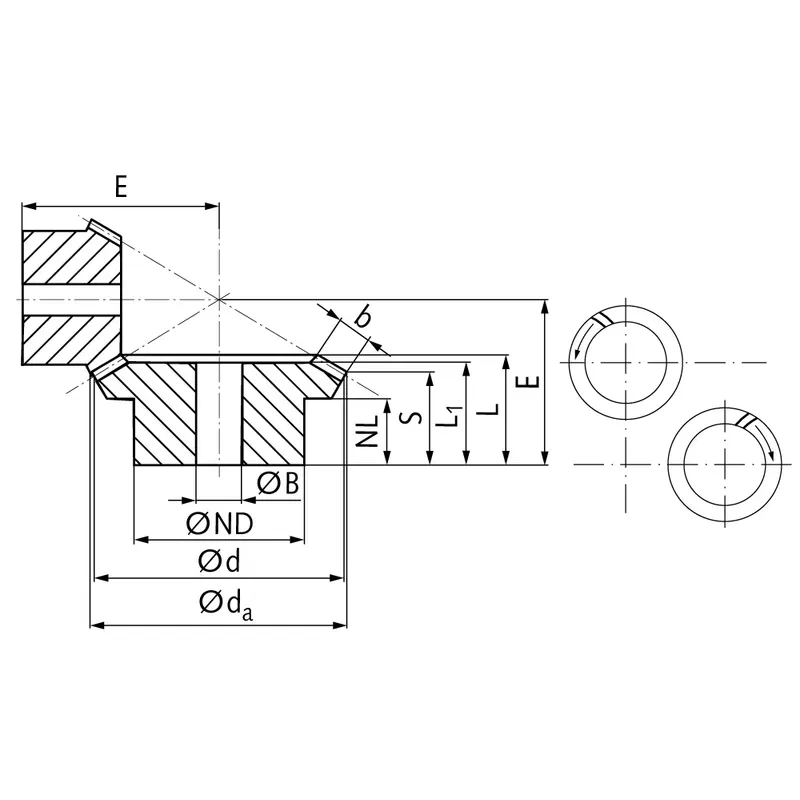 |
| Module | Number of teeth | da | d | ND | NL | L1 | L | S | b | BH7 | E | Torque* | Weight |
| mm | mm | mm | mm | mm | mm | mm | mm | mm | mm | Ncm | g | ||
| 1,5 | 13 | 36,7 | 33,9 | 22 | 11 | 21,6 | 24,1 | 16,0 | 10 | 12 | 38,5 | 11,3 | 216 |
| 1,5 | 18 | 48,5 | 47,0 | 30 | 11 | 20,9 | 24,7 | 18,9 | 10 | 15 | 34,8 | 15,7 | 216 |
Advantages of Steel Spiral Bevel Gears
- Enhanced Load Capacity
Steel spiral bevel gears are made from high-strength alloys like 42CrMo4, enabling them to handle heavy loads and high torque. Their robust construction ensures durability under extreme stress, making them ideal for demanding applications such as industrial machinery and automotive differentials. - Smooth and Quiet Operation
The spiral tooth design allows gradual tooth engagement, significantly reducing noise and vibration compared to straight bevel gears. This smooth meshing enhances operational efficiency and comfort, particularly in high-speed applications like marine propulsion systems or precision manufacturing equipment. - High Efficiency
The curved, helical teeth of spiral bevel gears provide a larger contact area, improving power transmission efficiency. This minimizes energy loss, making them suitable for applications requiring optimal performance, such as aerospace systems or heavy-duty power tools, where efficiency is critical. - Reduced Wear and Tear
The gradual tooth contact in spiral bevel gears distributes stress evenly, reducing wear on individual teeth. This prolongs gear lifespan and minimizes maintenance needs, making them cost-effective for long-term use in industries like mining or construction equipment manufacturing. - Versatility in Angles
Spiral bevel gears can transmit power between shafts at various angles, typically 90 degrees, but adaptable to other configurations. This flexibility makes them essential in complex machinery layouts, such as robotics or automotive systems, where precise angular power transfer is required. - Improved Precision and Stability
Precision manufacturing of spiral bevel gears ensures tight tolerances and minimal backlash. This results in stable, accurate motion transfer, critical for applications like CNC machines or vehicle transmissions, where consistent performance and reliability are paramount for operational success.
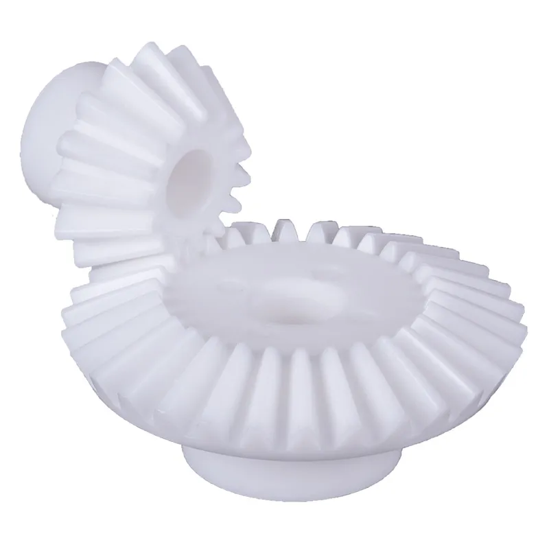
Spiral Bevel Gear vs. Straight Bevel Gear
| Aspect | Straight Bevel Gear | Spiral Bevel Gear |
|---|---|---|
| Teeth Design | Teeth are straight and cut along the axis on a cone. | Teeth are spiral-shaped and cut in the form of a spiral curve on the pitch cone. |
| Contact Scenario | Two teeth of the mating gears come into sudden contact, and the contact is always a line equal to the face width of the teeth. | Teeth of the mating gears come into contact gradually, starting with a point, then becoming a line. |
| Impact Loading | Teeth experience sudden impact or shock loading due to abrupt contact. | Teeth experience gradual loading, which minimizes shock and impact. |
| Noise Level | Sudden contact generates significant noise. | Smoother engagement results in quieter operation. |
| Vibration | Shock loading induces vibrations, making operation less smooth. | Gradual load buildup reduces vibration, ensuring smoother operation. |
| Cost | Easier to design and manufacture, making it less expensive. | Complex design and manufacturing processes result in higher costs, often 1.2–1.5 times more than straight bevel gears. |
| Thrust Force | Produces less thrust force on the bearings that hold the shafts. | Produces more thrust force on bearings due to the spiral tooth design. |
| Efficiency at High Speed | Less suitable for high-speed applications due to noise and vibration. | More efficient at high speed, with reduced noise and smoother operation. |
| Application | Commonly used in simple, low-speed, or low-cost applications. | Preferred for high-speed, high-performance applications where smoothness and durability are critical. |
 |  |
| Spiral Bevel Gear | Straight Bevel Gear |
Spiral Bevel Gear Maintenance Tips
- Regular Lubrication
Proper lubrication is essential to minimize friction and wear between the spiral teeth. Use high-quality gear oil recommended by the manufacturer and ensure the oil is applied consistently. Regularly check the lubricant for contamination or degradation and replace it as needed to maintain efficiency. - Inspect for Wear and Damage
Periodically examine the gear teeth for signs of wear, cracks, or damage. Look for pitting, scoring, or unusual wear patterns that could indicate misalignment or overloading. Addressing these issues early can prevent further damage and costly repairs. - Monitor Alignment
Ensure the gears are correctly aligned to avoid uneven load distribution and premature wear. Misalignment can cause increased noise, vibration, and stress on the teeth. Use precision tools to check alignment during installation and as part of routine maintenance. - Control Operating Conditions
Maintain optimal operating conditions by avoiding overloading and controlling the temperature. Excessive heat can degrade the lubricant and weaken the gear material. Use cooling systems if necessary, and operate the gears within their specified load and speed limits to ensure longevity. - Clean Regularly
Keep the gear system clean and free from dirt, debris, or contamination. Foreign particles can cause abrasion and accelerate wear on the gear teeth. Use proper sealing mechanisms to prevent contaminants from entering the system, and clean the area if contamination occurs.
Additional information
| Edited by | Yjx |
|---|