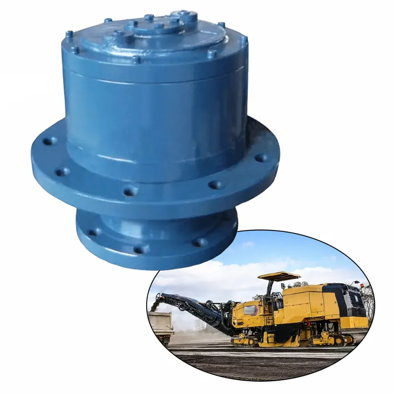
Planetary Slewing Drive Gearbox for Solar Tracking Systems
A planetary slewing drive gearbox for solar tracking systems is a sophisticated rotary drive mechanism designed to enable precise, controlled rotation of solar panels to optimize energy capture by following the sun’s path throughout the day. This slewing planetary gearbox integrates a high-precision planetary gear system with a slewing ring bearing, providing exceptional torque output, compact design, and superior load-bearing capacity for both radial and axial forces.
A planetary slewing drive gearbox for solar tracking systems is a sophisticated rotary drive mechanism designed to enable precise, controlled rotation of solar panels to optimize energy capture by following the sun's path throughout the day. This slewing planetary gearbox integrates a high-precision planetary gear system with a slewing ring bearing, providing exceptional torque output, compact design, and superior load-bearing capacity for both radial and axial forces. Unlike traditional worm gear alternatives, the planetary configuration delivers higher efficiency, reduced backlash, and a larger gear ratio in a single stage, making it ideal for single- or dual-axis solar trackers, heliostats, and concentrated photovoltaic (CPV) applications.
![]()
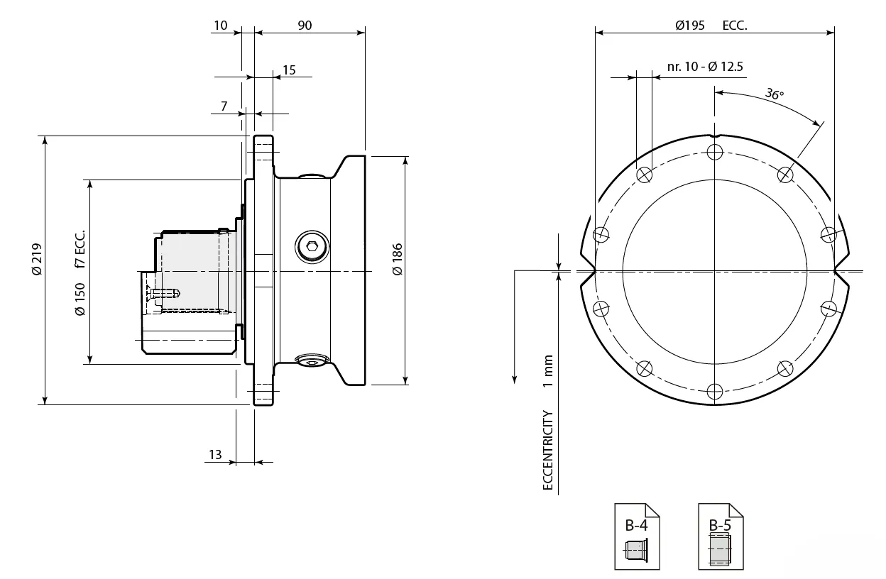
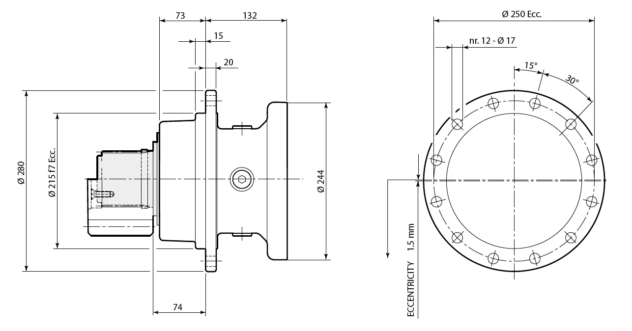
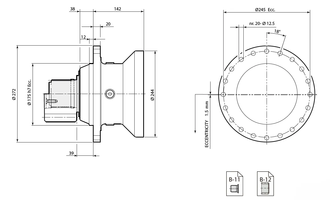
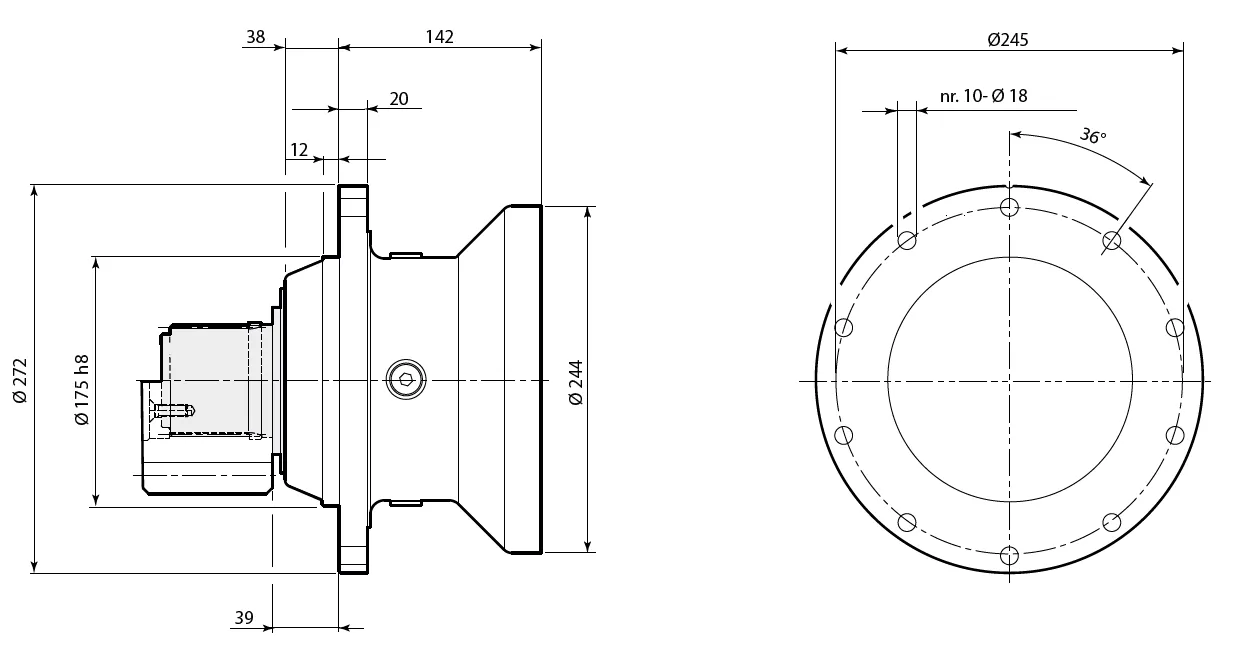
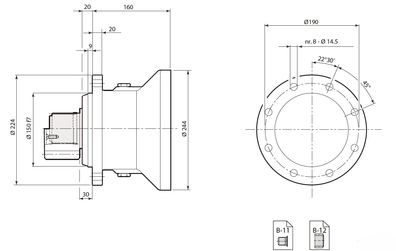
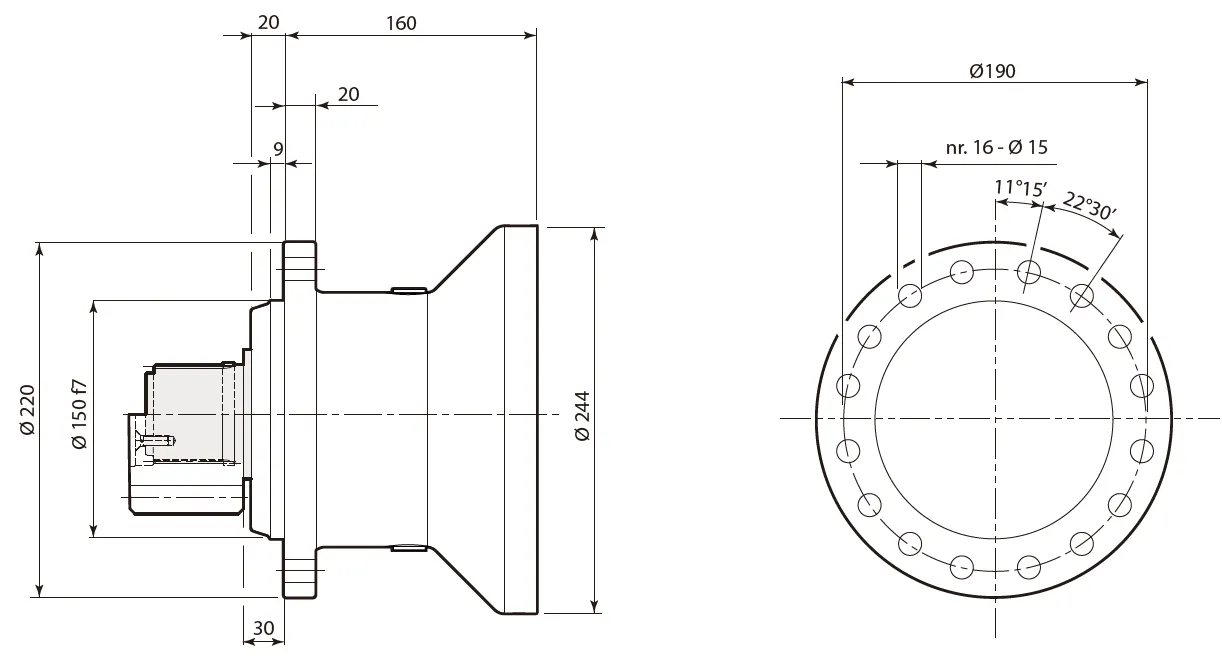
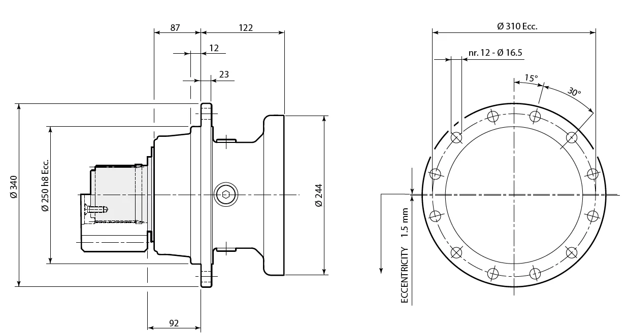
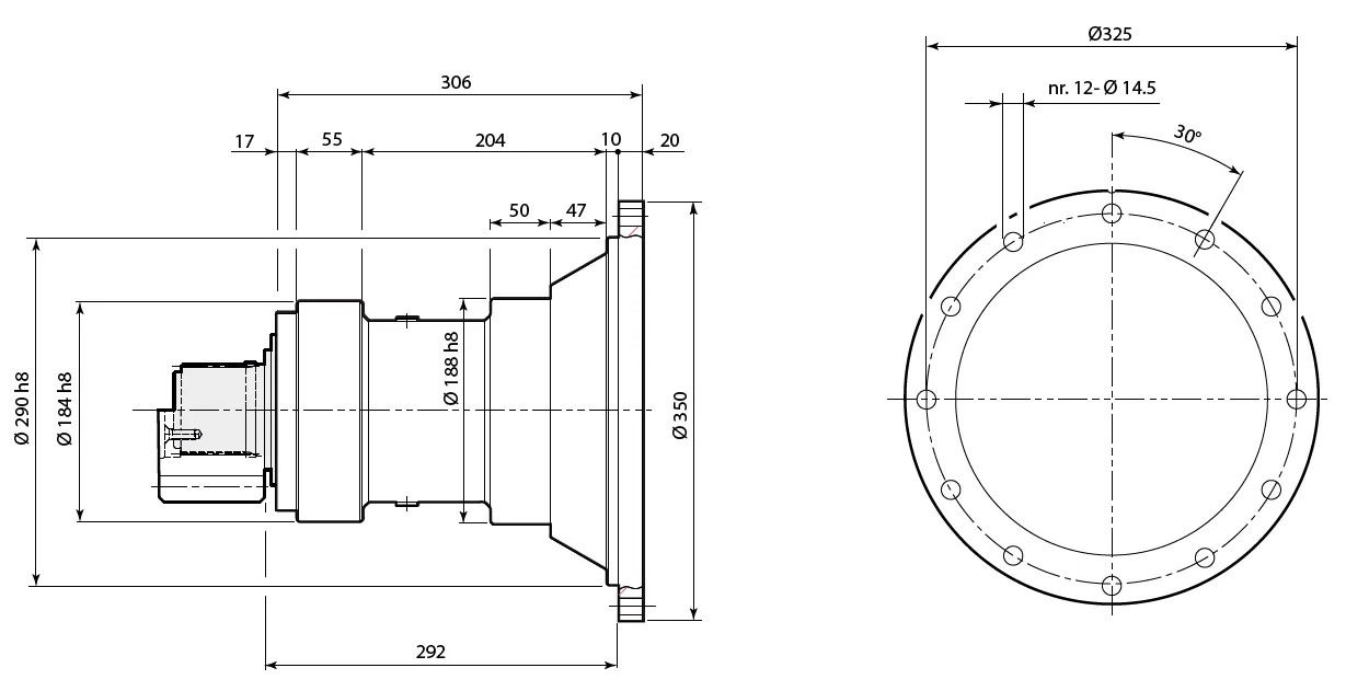
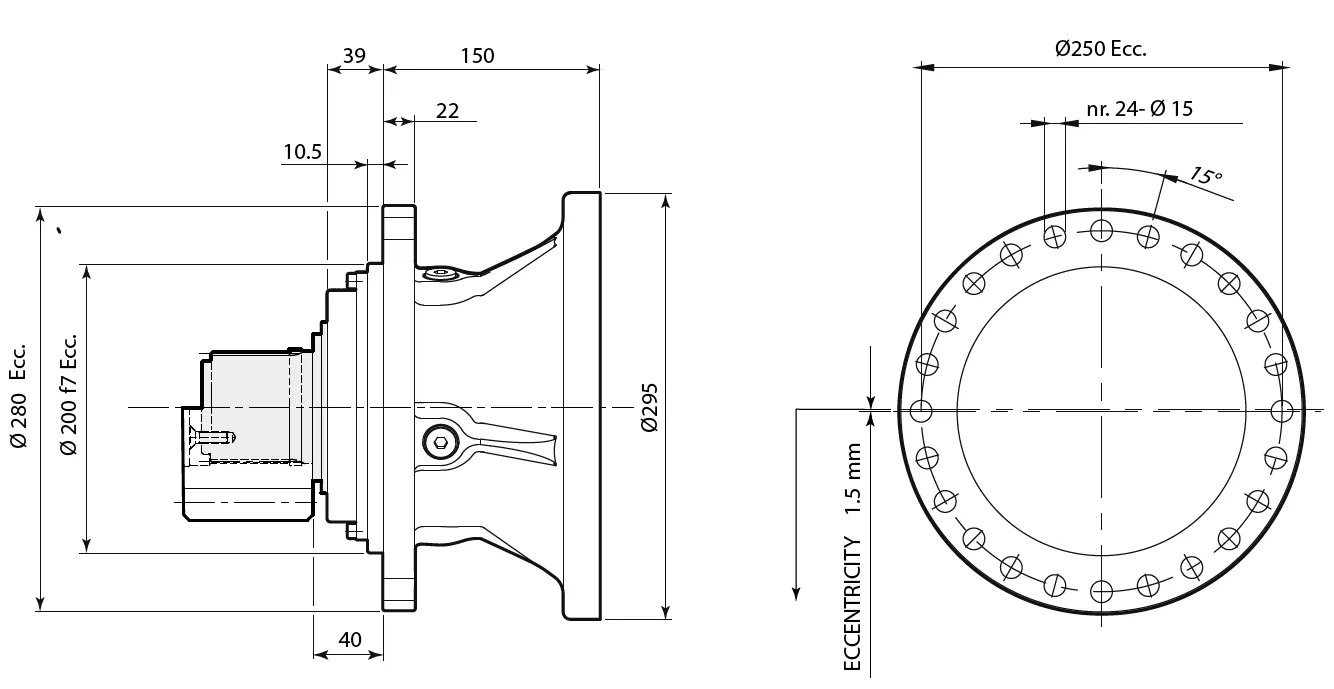
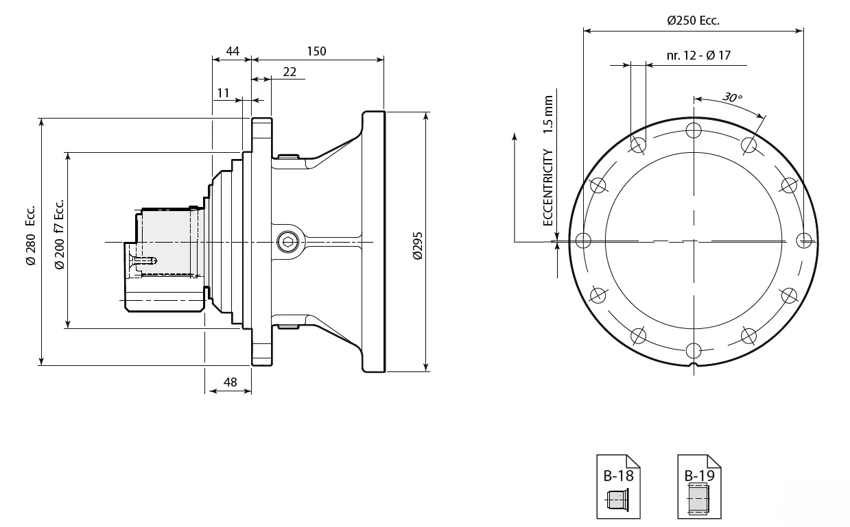
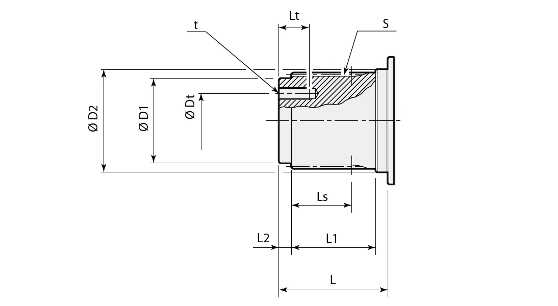
Planetary Slewing Drive Dimensions
RE 240
Support: DBS

Support: Tecc
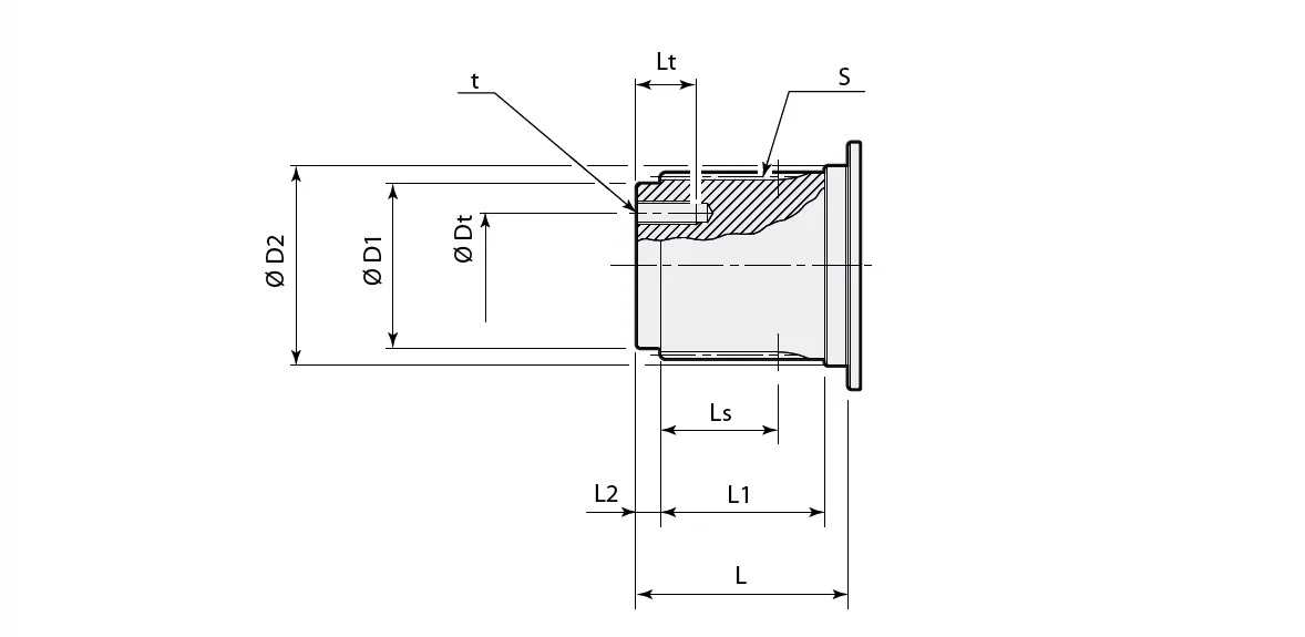
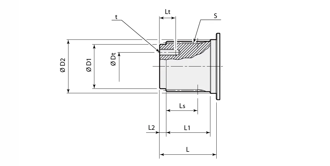
Splined Shaft:
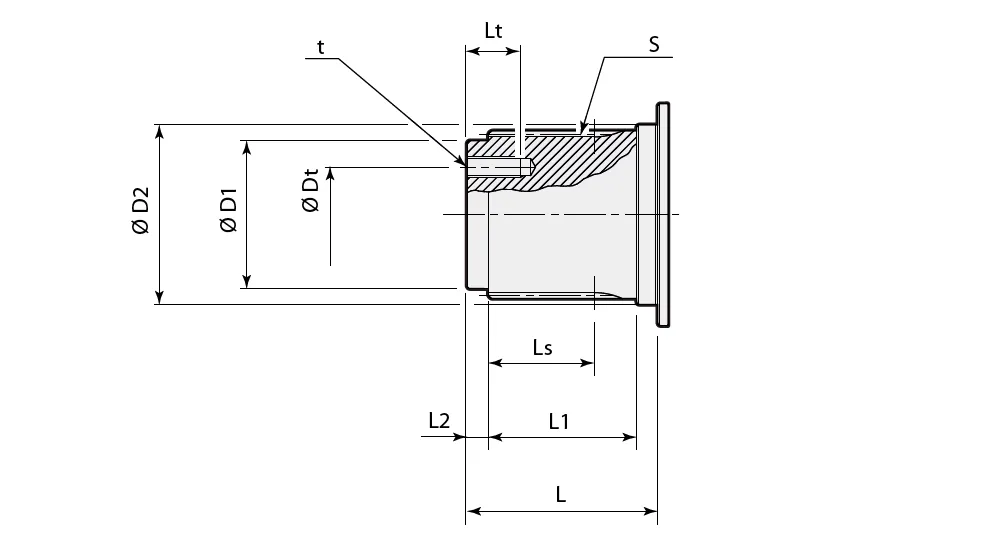
| Supporto Support | ØD1 | ØD2 | S | Ls | L | L1 | L2 | t | ØDt | Lt |
| [ mm ] | ||||||||||
| DBS | 50 h7 | 60 h6 | DIN5482 B58x53 | 37 | 68.3 | 50 | 8 | M10 (n° 3) | 32 | 21 |
| Tecc | 50 h7 | 60 h6 | DIN5482 B58x53 | 37 | 68.3 | 50 | 8 | M10 (n° 3) | 32 | 21 |
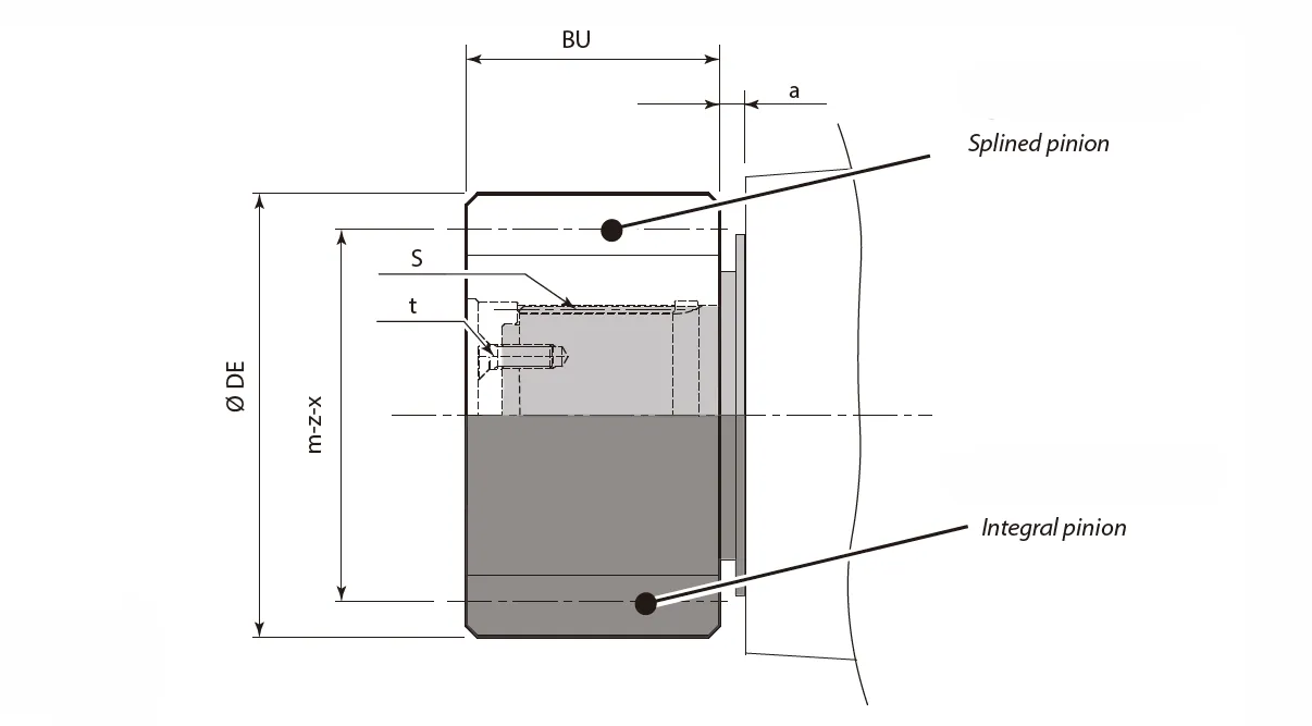
Pinions:
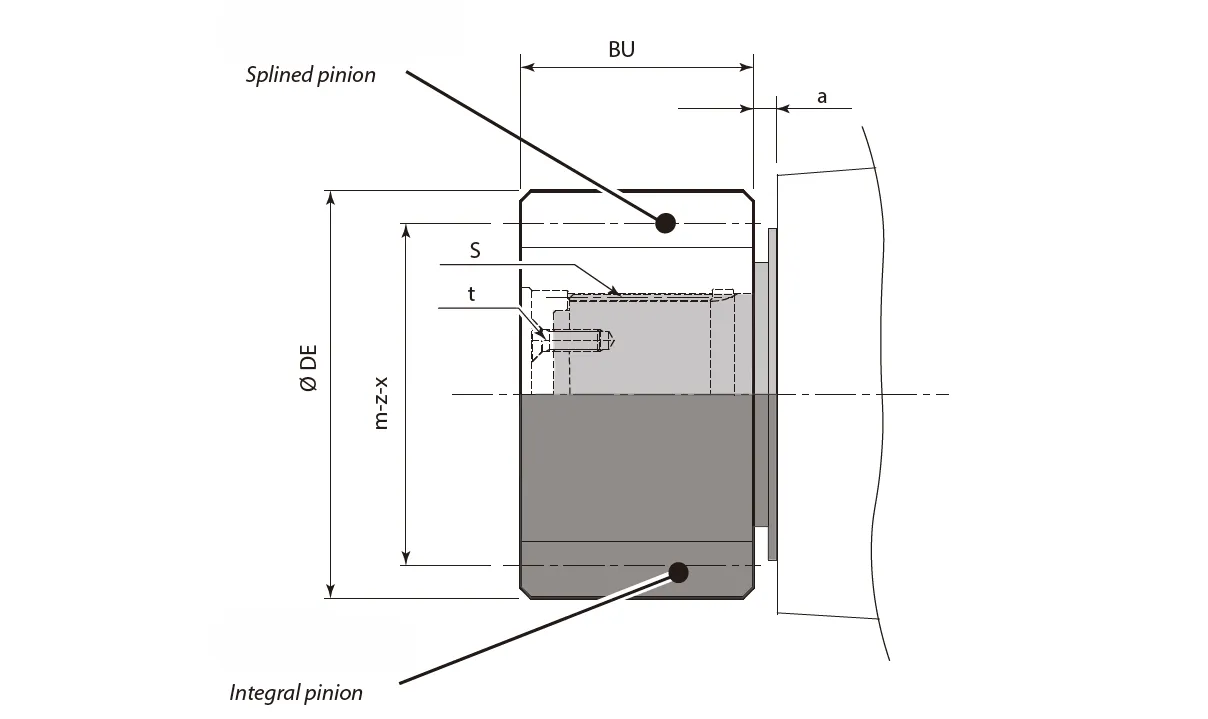
| Support | m | z | x | ØDE | BU | a | S | t | Tmax | |
| [mm] | Static [Nm] | Dynamic [Nm] | ||||||||
| DBS | 6 | 15 | 0.5 | 108 | 88 | 2 | - | - | 6000 | 5400 |
| 8 | 9 | 0.5 | 95.2 | 96 | 0.5 | - | - | 5000 | 4500 | |
| 10 | 11 | 0.5 | 137 | 68 | 2 | - | - | 6300 | 5670 | |
| 14 | 13 | 0.5 | 224 | 70 | 2 | DIN5482 B58x53 | M10 (n° 3) | 6300 | 5670 | |
| Tecc | 6 | 18 | 0 | 120 | 70 | 13.5 | DIN5482 B58x53 | M10 (n° 3) | 6000 | 5400 |
| 8 | 10 | 0.5 | 104 | 80 | 13.5 | - | - | 5000 | 4500 | |
| 8 | 14 | 0.5 | 136 | 80 | 23.5 | DIN5482 B58x53 | M10 (n° 3) | 6300 | 5670 | |
| 10 | 13 | 0 | 150 | 80 | 3.5 | DIN5482 B58x53 | M10 (n° 3) | 6300 | 5670 | |
| 14 | 13 | 0,5 | 224 | 70 | 2 | DIN5482 B58x53 | M10 (n° 3) | 6500 | 5670 | |
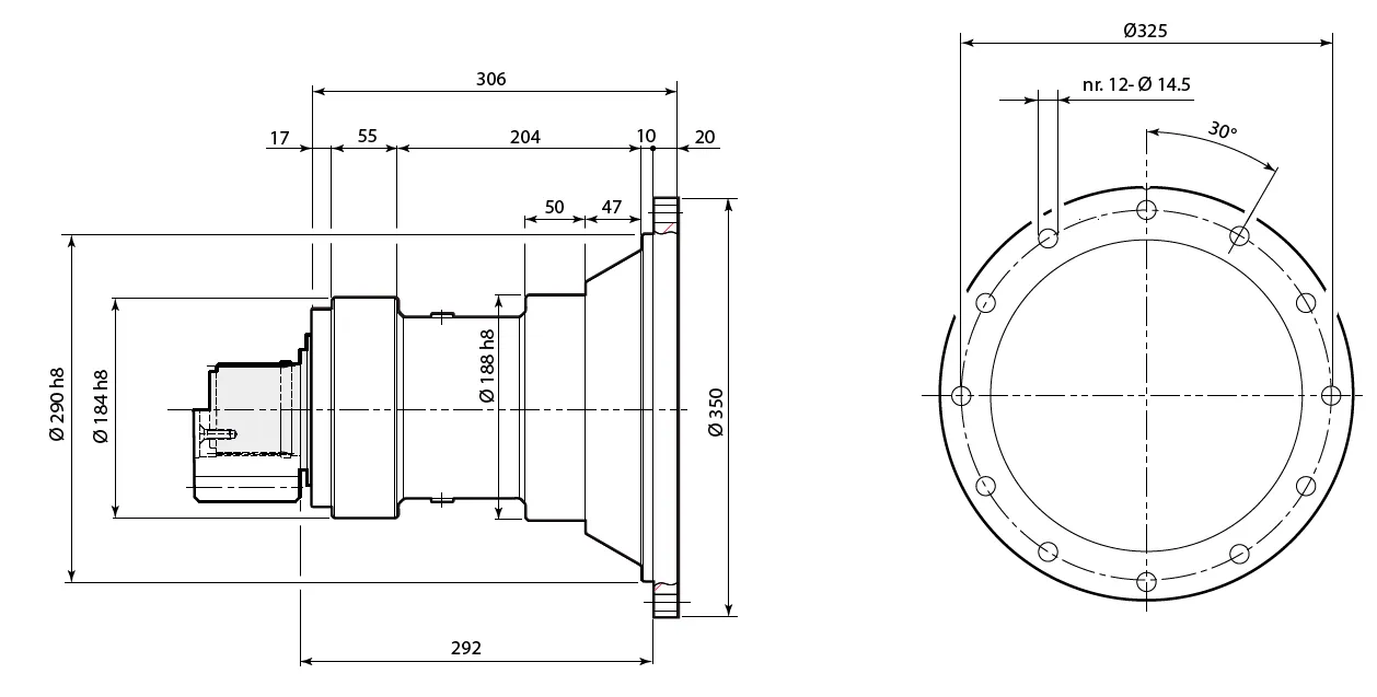
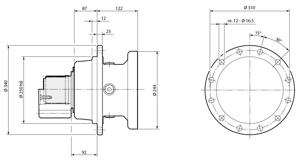
RE 310/510
Support: DBS
Support: Tecc
Support: T6
Support: T8

Support: T18
Support: NR
Support: NR3
Shaft:
| Support | ØD1 | ØD2 | S | Ls | L | L1 | L2 | t | ØDt | Lt |
| [ mm ] | ||||||||||
| DBS | 50 h7 | 60 h6 | DIN5482 B58x53 | 46 | 78 | 60 | 8 | M10 (n° 3) | 32 | 20 |
| Tecc | 50 h7 | 60 h6 | DIN5482 B58x53 | 46 | 78 | 60 | 8 | M10 (n° 3) | 32 | 20 |
| T6 | 50 h7 | 60 h6 | DIN5482 B58x53 | 46 | 78 | 60 | 8 | M10 (n° 3) | 32 | 20 |
| T8 | 50 h7 | 60 h6 | DIN5482 B58x53 | 46 | 78 | 60 | 8 | M10 (n° 3) | 32 | 20 |
| T18 | 62 F7 | 72 F7 | DIN5482 B70x64 | 51 | 90 | 70 | 10 | M10 (n° 3) | 40 | 22 |
| NR | 50 h7 | 60 h6 | DIN5482 B58x53 | 37 | 68.5 | 50 | 8 | M10 (n° 3) | 32 | 20 |
| NR3 | 50 h7 | 60 h6 | DIN5482 B58x53 | 37 | 68.5 | 50 | 8 | M10 (n° 3) | 32 | 20 |
Pinions:
| Support | m | z | x | ØDE | BU | a | S | t | Tmax | |
| [mm] | Static [Nm] | Dynamic [Nm] | ||||||||
| DBS | 8 | 11 | 0.5 | 112.2 | 78 | 7 | - | - | 10500 | 9450 |
| 9 | 13 | 0.5 | 144 | 75 | 7 | - | - | 10500 | 9450 | |
| 10 | 11 | 0.5 | 137 | 78 | 7 | - | - | 10500 | 9450 | |
| 10 | 15 | 0 | 170 | 90 | 10 | - | - | 10500 | 9450 | |
| 12 | 10 | 0.5 | 155 | 95 | 7 | - | - | 10500 | 9450 | |
| 12 | 11 | 0.5 | 166.8 | 80 | 7 | - | - | 10500 | 9450 | |
| Tecc | 6 | 13 | 0.65 | 97.2 | 65 | 27 | - | - | 6900 | 6210 |
| 8 | 11 | 0.5 | 111.2 | 88 | 4 | - | - | 8300 | 7470 | |
| 8 | 15 | 0 | 136 | 75 | 11 | DIN5482 B58x53 | M10 (n° 3) | 10400 | 9360 | |
| 10 | 10 | 0.5 | 130 | 90 | 3 | - | - | 9500 | 8550 | |
| 14 | 14 | 0.5 | 236.6 | 100 | 1 | DIN5482 B58x53 | M10 (n° 3) | 10500 | 9450 | |
| T6 T8 | 10 | 13 | 0.6 | 161 | 86 | 17 | - | - | 10500 | 9450 |
| 10 | 14 | 0.5 | 168 | 80 | 2.5 | - | - | 10500 | 9450 | |
| 10 | 12 | 0.55 | 150.5 | 93 | 3 | - | - | 10500 | 9450 | |
| 12 | 10 | 0.5 | 155 | 108 | 5.5 | - | - | 10500 | 9450 | |
| T18 | 8 | 14 | 0 | 128 | 79.5 | 16 | DIN5482 B70x64 | M10 (n° 3) | 10500 | 9450 |
| 10 | 14 | 0.32 | 166.4 | 90 | 15 | 13200 | 11880 | |||
| 12 | 13 | 0.5 | 192 | 80 | 21 | 13200 | 11880 | |||
| 14 | 15 | 0.5 | 250.6 | 105 | 6 | 13200 | 11880 | |||
| NR NR3 | 5 | 22 | 0 | 120 | 50 | 27.5 | DIN5482 B58x53 | M10 (n° 3) | 9250 | 8325 |
| 8 | 11 | 0.5 | 110.8 | 79 | 10.5 | - | - | 9250 | 8325 | |
| 8 | 16 | 0.5 | 149.5 | 73 | 20.5 | - | - | 9250 | 8325 | |
| 10 | 11 | 0.5 | 139 | 100 | 12 | - | - | 9250 | 8325 | |
| 10 | 12 | 0.5 | 149 | 90 | 19.5 | - | - | 9250 | 8325 | |
RE 610
Support: DBS
Support: DBS2
Support: T18
Shaft:
| Support | ØD1 | ØD2 | S | Ls | L | L1 | L2 | t | ØDt | Lt |
| [ mm ] | ||||||||||
| DBS | 62 h7 | 72 h6 | DIN5482 B70x64 | 51 | 90 | 70 | 10 | M10 (n° 3) | 40 | 22 |
| DBS2 | 62 h7 | 72 h6 | DIN5482 B70x64 | 51 | 90 | 70 | 10 | M10 (n° 3) | 40 | 22 |
| T18 | 62 f7 | 72 f7 | DIN5482 B70x64 | 51 | 90 | 70 | 10 | M10 (n° 3) | 40 | 22 |
Pinions:

| Support | m | z | x | ØDE | BU | a | S | t | Tmax | |
| [mm] | Static [Nm] | Dynamic [Nm] | ||||||||
| DBS DBS2 | 8 | 14 | 0 | 128 | 79.5 | 15 | DIN 5482 B70x64 | M10 (n° 3) | 17500 | 15750 |
| 10 | 12 | 0.5 | 150 | 78 | 5 | - | - | 21500 | 19350 | |
| 10 | 13 | 0.5 | 160 | 85 | 19 | DIN 5482 B70x64 | M10 (n° 3) | 21000 | 18900 | |
| 10 | 14 | 0.5 | 170 | 90 | 5 | - | - | 24000 | 21600 | |
| 12 | 10 | 0 | 144 | 100 | 5 | - | - | 18500 | 16650 | |
| 12 | 12 | 0.5 | 180 | 100 | 5 | DIN 5482 B70x64 | M10 (n° 3) | 24000 | 21600 | |
| 12 | 14 | 0.5 | 204 | 105 | 5 | - | - | 24000 | 21600 | |
| 14 | 11 | 0.5 | 194.6 | 105 | 4 | - | - | 24000 | 21600 | |
| T18 | 8 | 20 | 0 | 176 | 115 | 15 | DIN 5482 B70x64 | M10 (n° 3) | 14500 | 13050 |
| 10 | 11 | 0.681 | 141 | 85 | 6 | - | - | 12000 | 10800 | |
| 12 | 10 | 0.5 | 156 | 120 | 6 | - | - | 12000 | 10800 | |
| 12 | 11 | 0.525 | 168.61 | 110 | 6 | - | - | 13500 | 12150 | |
RE 810
Support: Tecc
Support: TRecc
Shaft:
| Support | ØD1 | ØD2 | S | Ls | L | L1 | L2 | t | ØDt | Lt |
| [ mm ] | ||||||||||
| Tecc | 62 f7 | 72 f7 | DIN5482 B70x64 | 51 | 90 | 70 | 10 | M10 (n° 3) | 40 | 22 |
| TRecc | ||||||||||
Pinions:

| Support | m | z | x | ØDE | BU | a | S | t | Tmax | |
| [mm] | Static [Nm] | Dynamic [Nm] | ||||||||
| Tecc | 8 | 14 | 0 | 128 | 79.5 | 11.5 | DIN 5482 B70x64 | M10 (n° 3) | 10500 | 9450 |
| 9 | 15 | 0 | 152.64 | 101 | 6.5 | - | - | 12500 | 11250 | |
| 10 | 14 | 0.5 | 169 | 90 | 1.5 | DIN 5482 B70x64 | M10 (n° 3) | 14500 | 13050 | |
| 12 | 13 | 0.5 | 192 | 95 | 32.5 | 13500 | 12150 | |||
| 14 | 15 | 0.5 | 250.6 | 105 | 1.5 | 21000 | 18900 | |||
| TRecc | 8 | 15 | 0.3 | 140 | 80 | 13.5 | DIN 5482 B70x64 | M10 (n° 3) | 15200 | 13680 |
| 10 | 13 | 0.5 | 160 | 90 | 5.5 | - | - | 17800 | 16020 | |
| 10 | 18 | 0 | 198 | 80 | 5.5 | - | - | 23800 | 21420 | |
| 12 | 12 | 0.5 | 180 | 100 | 3.5 | DIN 5482 B70x64 | M10 (n° 3) | 19000 | 17100 | |
| 12 | 14 | 0.5 | 199 | 100 | 33.5 | 16000 | 14400 | |||
Characteristic of Planetary Slewing Drive for Solar Tracking Systems
- High Torque Output for Optimal Performance
Planetary slewing drives are designed to deliver exceptional torque, enabling precise and reliable rotation of solar panels. This high torque capacity ensures stability and smooth operation, even under heavy loads, strong winds, or demanding environmental conditions, making them ideal for maximizing solar energy capture throughout the day. - Compact and Space-Saving Design
The planetary gear system in planetary slew drives offers a compact design while maintaining superior performance. This space-saving feature allows for easy integration into solar tracking systems, reducing overall system size and weight without compromising on efficiency or durability, a critical factor for modern solar installations. - Exceptional Load-Bearing Capacity
Equipped with a slewing ring bearing, these planetary slewing gearboxes handle both radial and axial loads effectively. Their robust construction ensures they can support the weight of large solar panels while withstanding external forces such as wind, snow, or vibrations, ensuring long-term reliability and consistent performance. - High Efficiency and Reduced Backlash
Compared to traditional worm gear systems, planetary slewing drive gearboxes achieve significantly higher efficiency. Their design minimizes energy losses and reduces backlash, allowing for accurate positioning of solar panels. This precision ensures the panels follow the sun’s movement precisely, improving energy yield and overall system efficiency. - Durable and Weather-Resistant Construction
Designed for outdoor applications, slewing planetary gearboxes are built with weather-resistant materials and coatings to withstand harsh environmental conditions. They are engineered to operate smoothly in extreme temperatures, high humidity, or dusty environments, making them highly durable and suitable for long-term use in solar tracking systems. - Customizable for Single- or Dual-Axis Systems
Slewing drive planetary gearboxes can be tailored to meet the needs of single- or dual-axis solar trackers. This flexibility allows for integration into a wide range of solar applications, including photovoltaic (PV) panels, concentrated photovoltaic (CPV) systems, and heliostats, ensuring they meet diverse project requirements efficiently.
![]()
![]()
Slewing Drive Planetary Gearbox Application Scenarios
- Solar Tracking Systems
These gearboxes facilitate the precise orientation of photovoltaic panels to follow the sun's trajectory, enhancing energy efficiency in single- and dual-axis trackers, thereby maximizing solar energy harvest in utility-scale farms and concentrated solar power plants under varying weather conditions. - Wind Turbines
Integrated into yaw and pitch control mechanisms, slewing drive planetary gearboxes enable the adjustment of turbine blades and nacelle rotation to optimize wind capture, ensuring reliable performance and structural integrity in onshore and offshore wind energy installations. - Construction Cranes
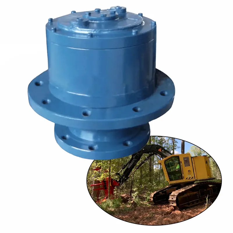
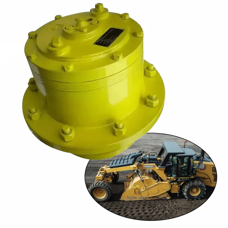
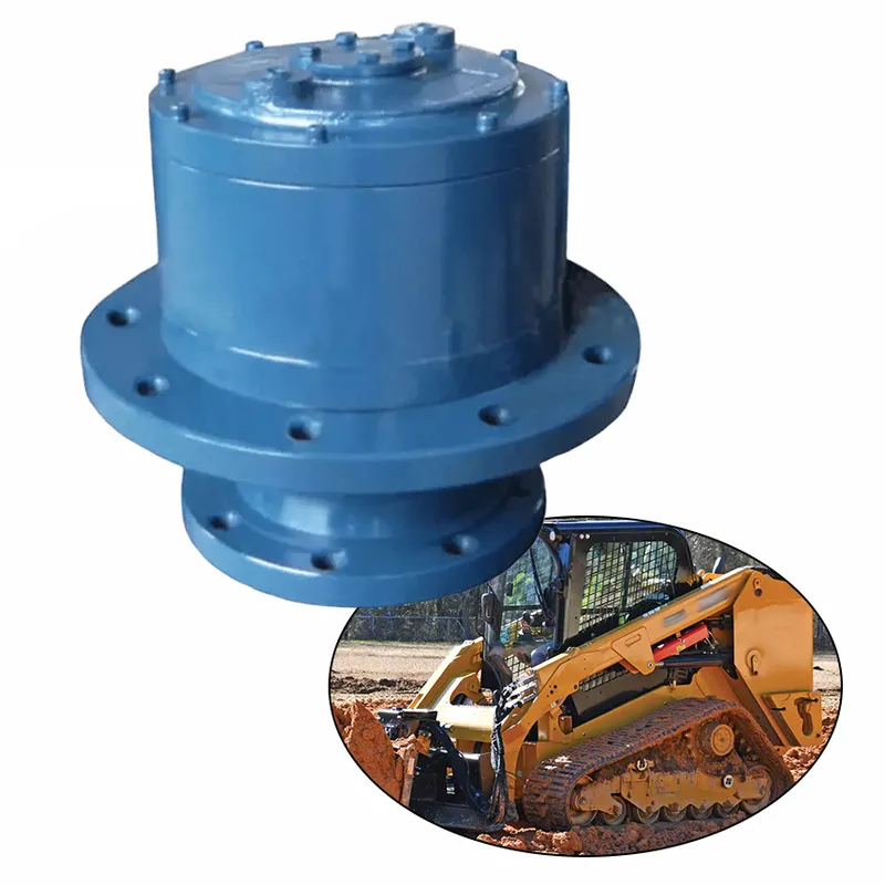
Utilized in tower cranes, mobile cranes, and harbor cranes, these gearboxes provide controlled slewing motion for lifting and positioning heavy loads, enhancing safety, operational efficiency, and load-bearing capacity on construction sites and industrial yards. - Excavators and Heavy Machinery
In excavators, bulldozers, and other earthmoving equipment, slewing drive planetary gearboxes support 360-degree rotation of upper structures, enabling precise digging, loading, and material handling in mining, infrastructure development, and demolition projects with high torque demands. - Robotics and Automation
Applied in industrial robots, automated guided vehicles (AGVs), and laser cutting machines, these gearboxes deliver accurate rotational control for multi-axis movements, improving productivity in manufacturing lines, warehousing, and precision engineering tasks requiring minimal backlash. - Satellite and Antenna Positioning
For satellite dishes, radar systems, and communication antennas, slewing drive planetary gearboxes ensure stable and precise alignment for signal transmission and reception, supporting applications in telecommunications, defense, and broadcasting with resistance to environmental vibrations.
 |  |
| Planetary Slewing Drive for Wind Turbines | Planetary Slewing Drive for Tower Cranes |
 |  |
| Planetary Slewing Drive for Excavators | Planetary Slewing Drive for Deck Cranes |
Planetary Slewing Drive Gearbox Installation Steps
- Preparation and Inspection
Before installation, carefully inspect the planetary slewing drive gearbox for any visible damage, dirt, or debris. Verify that all components, such as mounting brackets, bolts, and seals, are present and in good condition. Ensure the installation site is clean, level, and free from contaminants to prevent alignment issues. - Mounting Surface Alignment
Ensure the mounting surface is flat, rigid, and properly aligned with the gearbox. Any misalignment can lead to uneven load distribution, excessive wear, or operational inefficiencies. Use precision tools, such as a dial indicator or level, to check alignment and adjust the surface if necessary for optimal performance. - Secure the Gearbox to the Structure
Position the slewing drive gearbox onto the pre-aligned mounting surface. Secure it using high-strength bolts and washers, following the manual’s torque specifications. Tighten bolts diagonally or in a cross-pattern to ensure uniform pressure and stability, reducing the risk of mechanical failure during operation. - Connect the Driving Motor or Actuator
Attach the driving motor or actuator to the input flange of the planetary gearbox. Align the motor shaft with the gearbox input shaft to avoid misalignment or vibration. Use flexible couplings or adapters if necessary, and ensure all fasteners are tightened to the specified torque values for a secure connection. - Lubrication and Seal Inspection
Check the gearbox's lubrication levels and ensure it is filled with the recommended gear oil or grease. Inspect the seals for any potential leaks and confirm they are properly installed. Adequate lubrication reduces friction, prevents overheating, and ensures smooth operation, extending the gearbox’s lifespan. - Testing and Final Adjustments
After installation, perform a test run to verify the gearbox’s functionality. Rotate the drive manually or electrically, ensuring smooth and noise-free operation. Check for proper alignment, secure mounting, and absence of leaks or vibrations. Make any necessary adjustments before fully integrating the gearbox into the system.
![]()
Additional information
| Edited by | Yjx |
|---|