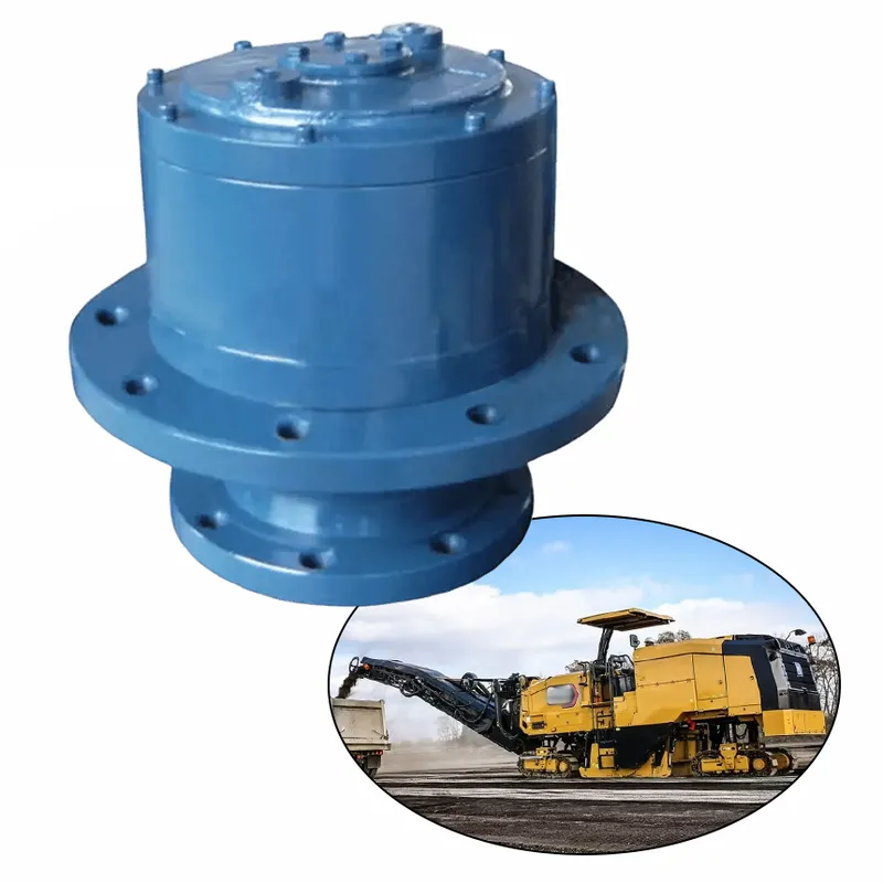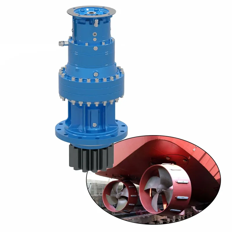
Planetary Slewing Drive Gearbox for Azimuth Thrusters
A planetary slewing drive gearbox for azimuth thrusters is a specialized, high-torque transmission system designed to facilitate precise 360-degree rotation of marine propulsion units. Utilizing a compact planetary gear arrangement, it consists of a central sun gear, multiple planet gears orbiting within a ring gear, and an output shaft connected to the slewing ring. This configuration provides exceptional load-bearing capacity, efficiency, and durability under harsh marine conditions, enabling azimuth thruster-steerable pods that house propellers to pivot seamlessly for enhanced vessel maneuverability, thrust vectoring, and dynamic positioning.
A planetary slewing drive gearbox for azimuth thrusters is a specialized, high-torque transmission system designed to facilitate precise 360-degree rotation of marine propulsion units. Utilizing a compact planetary gear arrangement, it consists of a central sun gear, multiple planet gears orbiting within a ring gear, and an output shaft connected to the slewing ring. This configuration provides exceptional load-bearing capacity, efficiency, and durability under harsh marine conditions, enabling azimuth thruster-steerable pods that house propellers to pivot seamlessly for enhanced vessel maneuverability, thrust vectoring, and dynamic positioning. Commonly employed in ships, offshore platforms, and harbor equipment, these slewing gearboxes ensure reliable performance with minimal backlash, high reduction ratios, and resistance to shock loads, often featuring sealed housings for protection against water and corrosion.
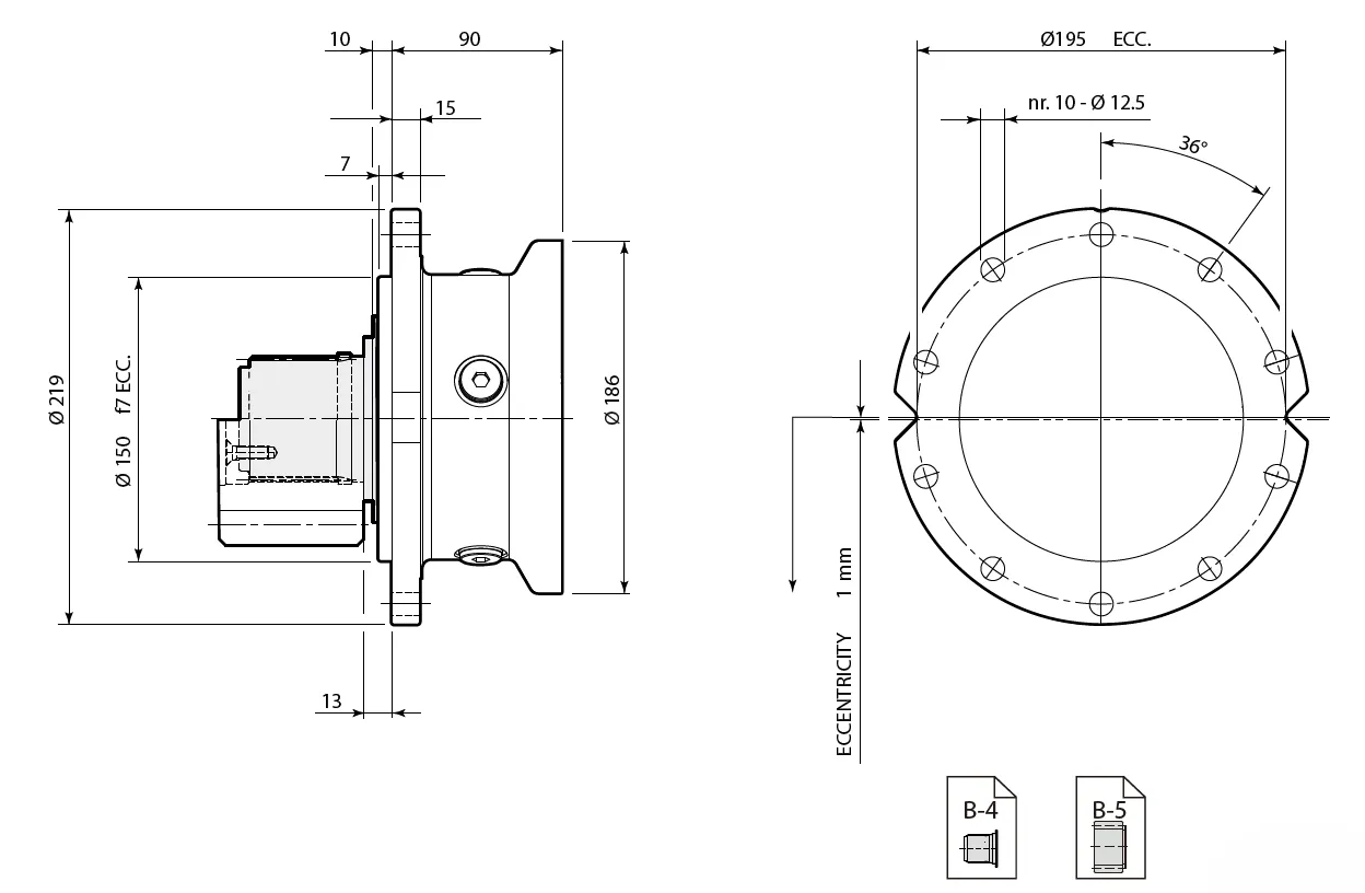
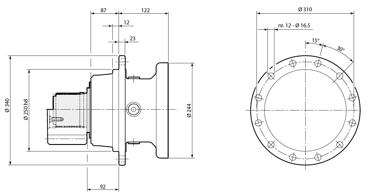
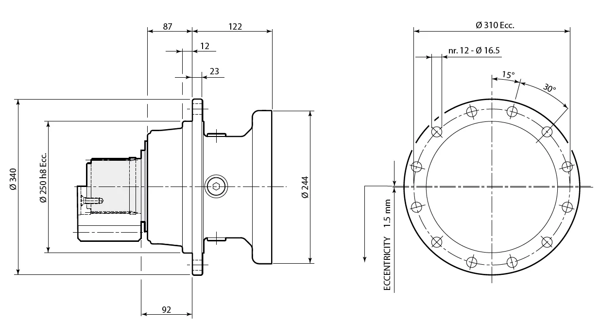
Planetary Slewing Drive Dimensions
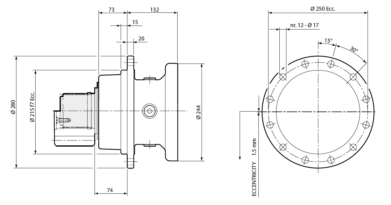
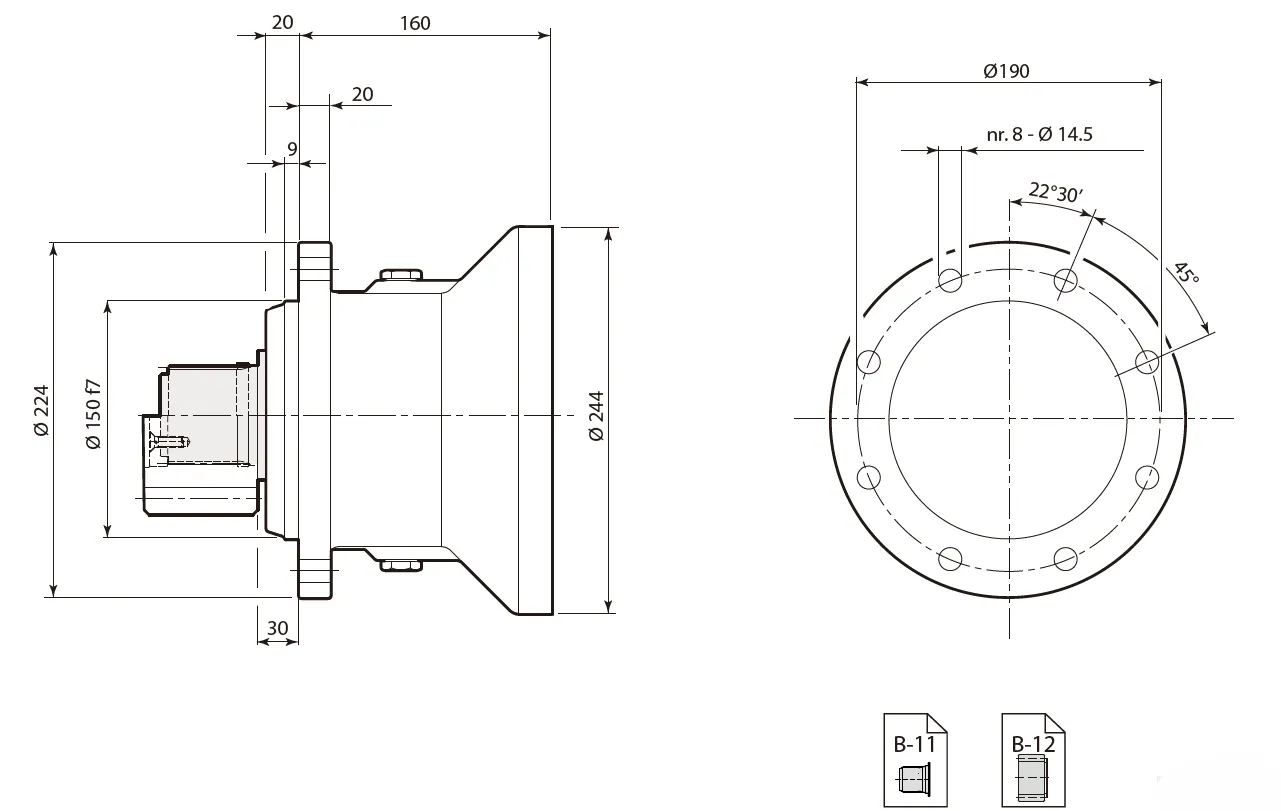
RE 240
Support: DBS

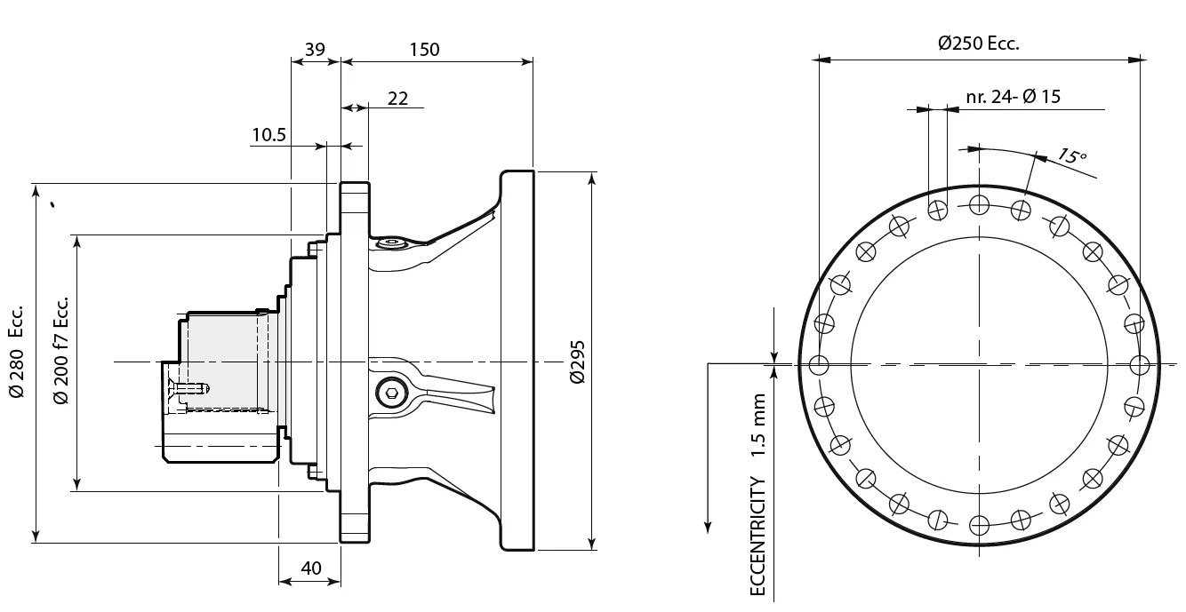
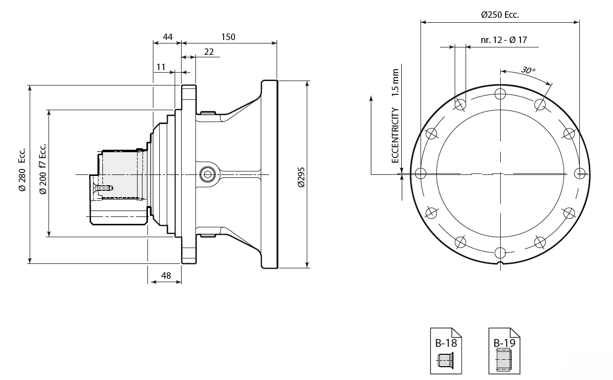
Support: Tecc
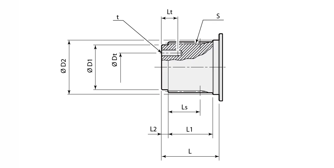
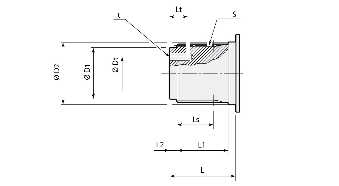
Splined Shaft:
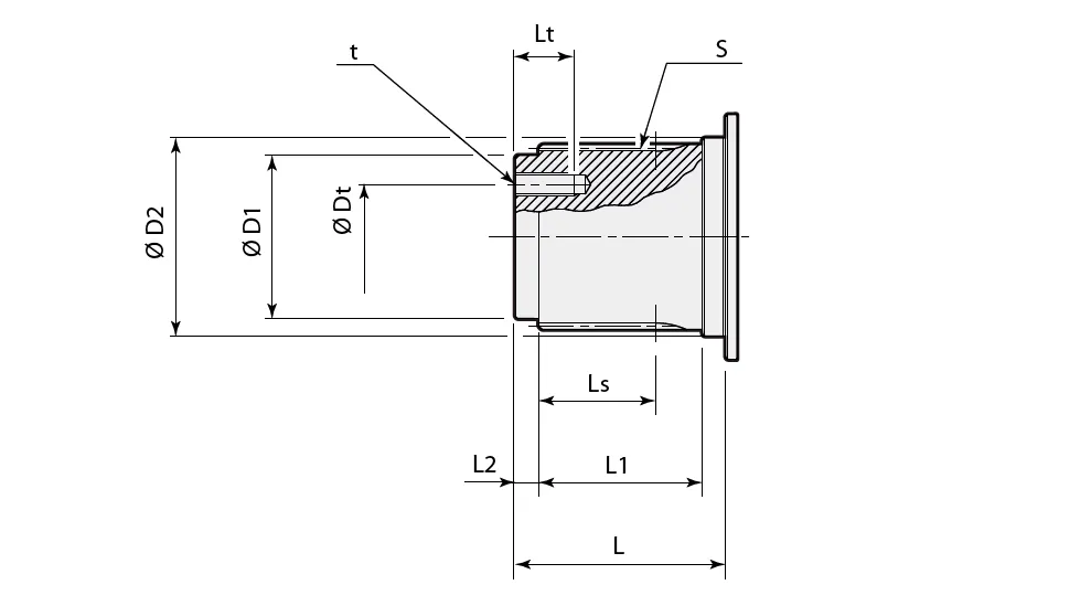
| Supporto Support | ØD1 | ØD2 | S | Ls | L | L1 | L2 | t | ØDt | Lt |
| [ mm ] | ||||||||||
| DBS | 50 h7 | 60 h6 | DIN5482 B58x53 | 37 | 68.3 | 50 | 8 | M10 (n° 3) | 32 | 21 |
| Tecc | 50 h7 | 60 h6 | DIN5482 B58x53 | 37 | 68.3 | 50 | 8 | M10 (n° 3) | 32 | 21 |
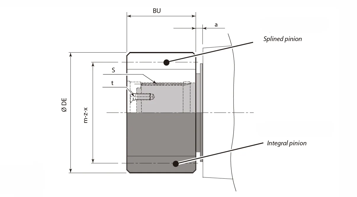
Pinions:
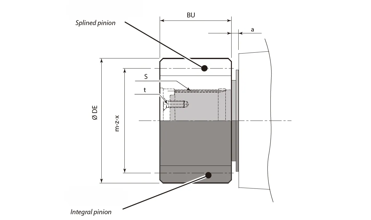
| Support | m | z | x | ØDE | BU | a | S | t | Tmax | |
| [mm] | Static [Nm] | Dynamic [Nm] | ||||||||
| DBS | 6 | 15 | 0.5 | 108 | 88 | 2 | - | - | 6000 | 5400 |
| 8 | 9 | 0.5 | 95.2 | 96 | 0.5 | - | - | 5000 | 4500 | |
| 10 | 11 | 0.5 | 137 | 68 | 2 | - | - | 6300 | 5670 | |
| 14 | 13 | 0.5 | 224 | 70 | 2 | DIN5482 B58x53 | M10 (n° 3) | 6300 | 5670 | |
| Tecc | 6 | 18 | 0 | 120 | 70 | 13.5 | DIN5482 B58x53 | M10 (n° 3) | 6000 | 5400 |
| 8 | 10 | 0.5 | 104 | 80 | 13.5 | - | - | 5000 | 4500 | |
| 8 | 14 | 0.5 | 136 | 80 | 23.5 | DIN5482 B58x53 | M10 (n° 3) | 6300 | 5670 | |
| 10 | 13 | 0 | 150 | 80 | 3.5 | DIN5482 B58x53 | M10 (n° 3) | 6300 | 5670 | |
| 14 | 13 | 0,5 | 224 | 70 | 2 | DIN5482 B58x53 | M10 (n° 3) | 6500 | 5670 | |
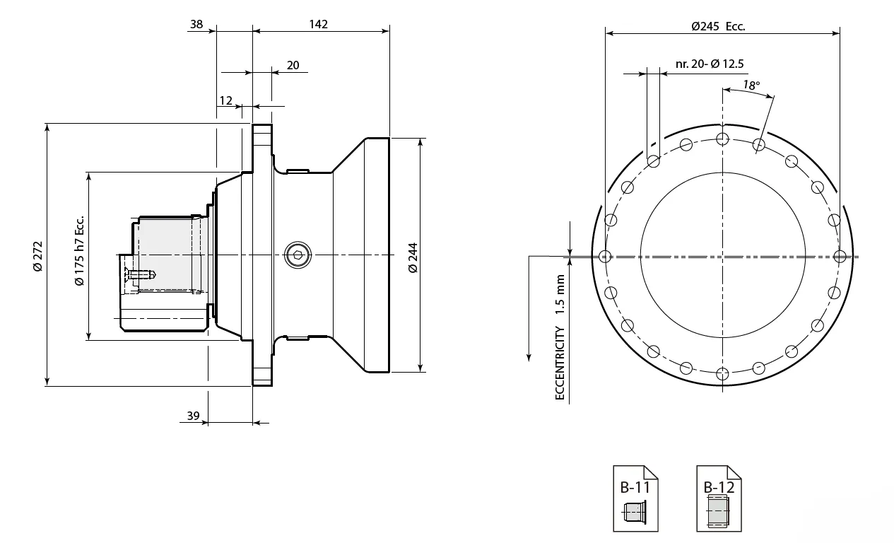
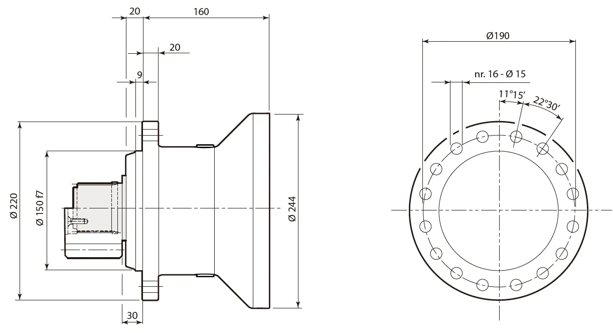
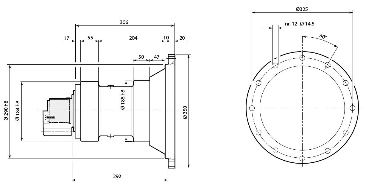
RE 310/510
Support: DBS
Support: Tecc
Support: T6
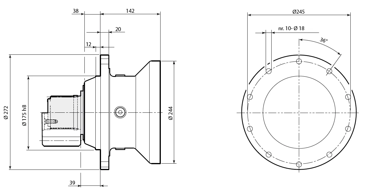
Support: T8

Support: T18
Support: NR
Support: NR3
Shaft:
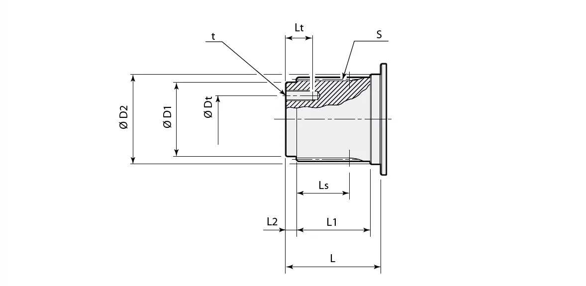
| Support | ØD1 | ØD2 | S | Ls | L | L1 | L2 | t | ØDt | Lt |
| [ mm ] | ||||||||||
| DBS | 50 h7 | 60 h6 | DIN5482 B58x53 | 46 | 78 | 60 | 8 | M10 (n° 3) | 32 | 20 |
| Tecc | 50 h7 | 60 h6 | DIN5482 B58x53 | 46 | 78 | 60 | 8 | M10 (n° 3) | 32 | 20 |
| T6 | 50 h7 | 60 h6 | DIN5482 B58x53 | 46 | 78 | 60 | 8 | M10 (n° 3) | 32 | 20 |
| T8 | 50 h7 | 60 h6 | DIN5482 B58x53 | 46 | 78 | 60 | 8 | M10 (n° 3) | 32 | 20 |
| T18 | 62 F7 | 72 F7 | DIN5482 B70x64 | 51 | 90 | 70 | 10 | M10 (n° 3) | 40 | 22 |
| NR | 50 h7 | 60 h6 | DIN5482 B58x53 | 37 | 68.5 | 50 | 8 | M10 (n° 3) | 32 | 20 |
| NR3 | 50 h7 | 60 h6 | DIN5482 B58x53 | 37 | 68.5 | 50 | 8 | M10 (n° 3) | 32 | 20 |
Pinions:
| Support | m | z | x | ØDE | BU | a | S | t | Tmax | |
| [mm] | Static [Nm] | Dynamic [Nm] | ||||||||
| DBS | 8 | 11 | 0.5 | 112.2 | 78 | 7 | - | - | 10500 | 9450 |
| 9 | 13 | 0.5 | 144 | 75 | 7 | - | - | 10500 | 9450 | |
| 10 | 11 | 0.5 | 137 | 78 | 7 | - | - | 10500 | 9450 | |
| 10 | 15 | 0 | 170 | 90 | 10 | - | - | 10500 | 9450 | |
| 12 | 10 | 0.5 | 155 | 95 | 7 | - | - | 10500 | 9450 | |
| 12 | 11 | 0.5 | 166.8 | 80 | 7 | - | - | 10500 | 9450 | |
| Tecc | 6 | 13 | 0.65 | 97.2 | 65 | 27 | - | - | 6900 | 6210 |
| 8 | 11 | 0.5 | 111.2 | 88 | 4 | - | - | 8300 | 7470 | |
| 8 | 15 | 0 | 136 | 75 | 11 | DIN5482 B58x53 | M10 (n° 3) | 10400 | 9360 | |
| 10 | 10 | 0.5 | 130 | 90 | 3 | - | - | 9500 | 8550 | |
| 14 | 14 | 0.5 | 236.6 | 100 | 1 | DIN5482 B58x53 | M10 (n° 3) | 10500 | 9450 | |
| T6 T8 | 10 | 13 | 0.6 | 161 | 86 | 17 | - | - | 10500 | 9450 |
| 10 | 14 | 0.5 | 168 | 80 | 2.5 | - | - | 10500 | 9450 | |
| 10 | 12 | 0.55 | 150.5 | 93 | 3 | - | - | 10500 | 9450 | |
| 12 | 10 | 0.5 | 155 | 108 | 5.5 | - | - | 10500 | 9450 | |
| T18 | 8 | 14 | 0 | 128 | 79.5 | 16 | DIN5482 B70x64 | M10 (n° 3) | 10500 | 9450 |
| 10 | 14 | 0.32 | 166.4 | 90 | 15 | 13200 | 11880 | |||
| 12 | 13 | 0.5 | 192 | 80 | 21 | 13200 | 11880 | |||
| 14 | 15 | 0.5 | 250.6 | 105 | 6 | 13200 | 11880 | |||
| NR NR3 | 5 | 22 | 0 | 120 | 50 | 27.5 | DIN5482 B58x53 | M10 (n° 3) | 9250 | 8325 |
| 8 | 11 | 0.5 | 110.8 | 79 | 10.5 | - | - | 9250 | 8325 | |
| 8 | 16 | 0.5 | 149.5 | 73 | 20.5 | - | - | 9250 | 8325 | |
| 10 | 11 | 0.5 | 139 | 100 | 12 | - | - | 9250 | 8325 | |
| 10 | 12 | 0.5 | 149 | 90 | 19.5 | - | - | 9250 | 8325 | |
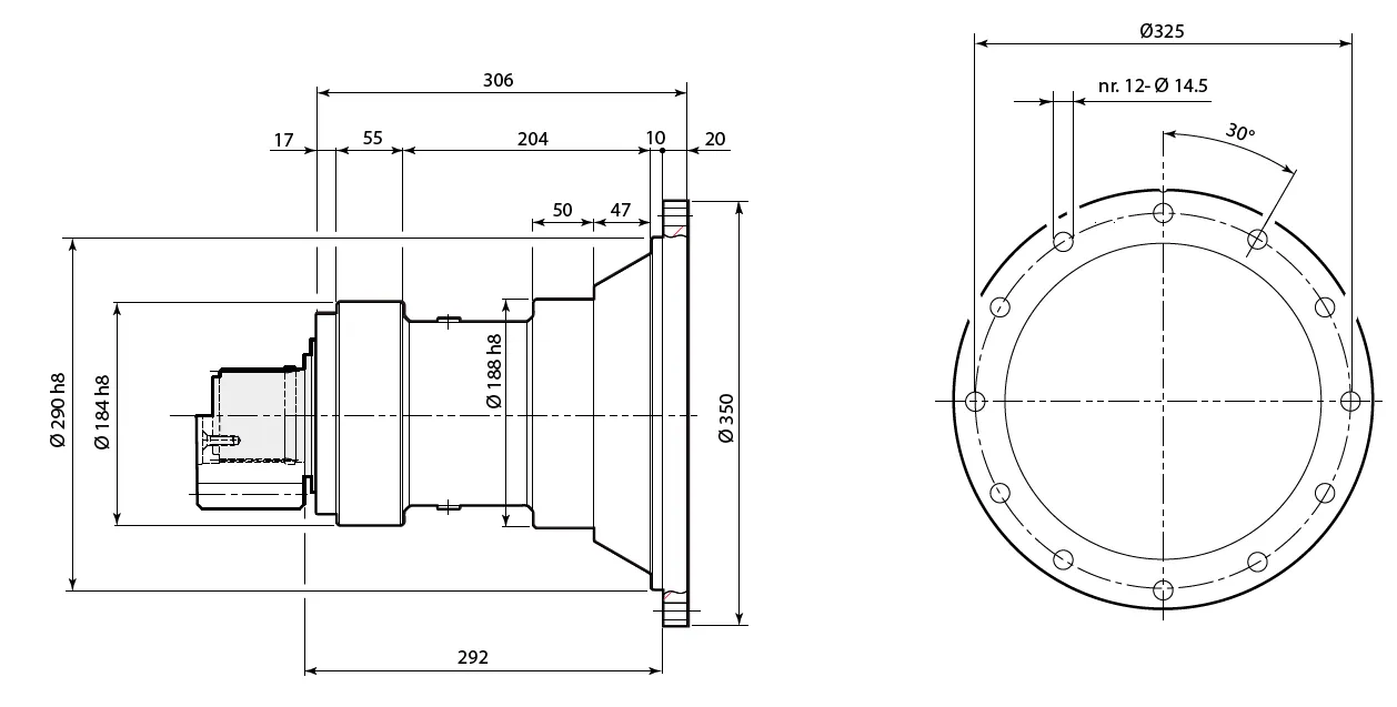
RE 610
Support: DBS
Support: DBS2
Support: T18
Shaft:
| Support | ØD1 | ØD2 | S | Ls | L | L1 | L2 | t | ØDt | Lt |
| [ mm ] | ||||||||||
| DBS | 62 h7 | 72 h6 | DIN5482 B70x64 | 51 | 90 | 70 | 10 | M10 (n° 3) | 40 | 22 |
| DBS2 | 62 h7 | 72 h6 | DIN5482 B70x64 | 51 | 90 | 70 | 10 | M10 (n° 3) | 40 | 22 |
| T18 | 62 f7 | 72 f7 | DIN5482 B70x64 | 51 | 90 | 70 | 10 | M10 (n° 3) | 40 | 22 |
Pinions:

| Support | m | z | x | ØDE | BU | a | S | t | Tmax | |
| [mm] | Static [Nm] | Dynamic [Nm] | ||||||||
| DBS DBS2 | 8 | 14 | 0 | 128 | 79.5 | 15 | DIN 5482 B70x64 | M10 (n° 3) | 17500 | 15750 |
| 10 | 12 | 0.5 | 150 | 78 | 5 | - | - | 21500 | 19350 | |
| 10 | 13 | 0.5 | 160 | 85 | 19 | DIN 5482 B70x64 | M10 (n° 3) | 21000 | 18900 | |
| 10 | 14 | 0.5 | 170 | 90 | 5 | - | - | 24000 | 21600 | |
| 12 | 10 | 0 | 144 | 100 | 5 | - | - | 18500 | 16650 | |
| 12 | 12 | 0.5 | 180 | 100 | 5 | DIN 5482 B70x64 | M10 (n° 3) | 24000 | 21600 | |
| 12 | 14 | 0.5 | 204 | 105 | 5 | - | - | 24000 | 21600 | |
| 14 | 11 | 0.5 | 194.6 | 105 | 4 | - | - | 24000 | 21600 | |
| T18 | 8 | 20 | 0 | 176 | 115 | 15 | DIN 5482 B70x64 | M10 (n° 3) | 14500 | 13050 |
| 10 | 11 | 0.681 | 141 | 85 | 6 | - | - | 12000 | 10800 | |
| 12 | 10 | 0.5 | 156 | 120 | 6 | - | - | 12000 | 10800 | |
| 12 | 11 | 0.525 | 168.61 | 110 | 6 | - | - | 13500 | 12150 | |
RE 810
Support: Tecc
Support: TRecc
Shaft:
| Support | ØD1 | ØD2 | S | Ls | L | L1 | L2 | t | ØDt | Lt |
| [ mm ] | ||||||||||
| Tecc | 62 f7 | 72 f7 | DIN5482 B70x64 | 51 | 90 | 70 | 10 | M10 (n° 3) | 40 | 22 |
| TRecc | ||||||||||
Pinions:

| Support | m | z | x | ØDE | BU | a | S | t | Tmax | |
| [mm] | Static [Nm] | Dynamic [Nm] | ||||||||
| Tecc | 8 | 14 | 0 | 128 | 79.5 | 11.5 | DIN 5482 B70x64 | M10 (n° 3) | 10500 | 9450 |
| 9 | 15 | 0 | 152.64 | 101 | 6.5 | - | - | 12500 | 11250 | |
| 10 | 14 | 0.5 | 169 | 90 | 1.5 | DIN 5482 B70x64 | M10 (n° 3) | 14500 | 13050 | |
| 12 | 13 | 0.5 | 192 | 95 | 32.5 | 13500 | 12150 | |||
| 14 | 15 | 0.5 | 250.6 | 105 | 1.5 | 21000 | 18900 | |||
| TRecc | 8 | 15 | 0.3 | 140 | 80 | 13.5 | DIN 5482 B70x64 | M10 (n° 3) | 15200 | 13680 |
| 10 | 13 | 0.5 | 160 | 90 | 5.5 | - | - | 17800 | 16020 | |
| 10 | 18 | 0 | 198 | 80 | 5.5 | - | - | 23800 | 21420 | |
| 12 | 12 | 0.5 | 180 | 100 | 3.5 | DIN 5482 B70x64 | M10 (n° 3) | 19000 | 17100 | |
| 12 | 14 | 0.5 | 199 | 100 | 33.5 | 16000 | 14400 | |||
Key Features of Planetary Slewing Drive for Azimuth Thrusters
1. High Torque and Load-Bearing Capacity
Planetary slewing drives are designed to deliver immense torque and exceptional load-bearing capacity. The multi-gear engagement system, including a central sun gear and orbiting planet gears, evenly distributes loads, reducing stress on individual components. This ensures reliable performance in demanding marine applications, such as dynamic positioning and thrust vectoring.
2. Compact and Efficient Design
The compact configuration of planetary slewing gearboxes allows for a higher torque-to-weight ratio compared to traditional gear systems. This space-saving design is ideal for azimuth thrusters, where limited room is available. Moreover, the system enhances energy efficiency by minimizing power loss during rotation, improving overall vessel performance.
3. 360-Degree Rotation with Precision
Planetary slewing drive gearboxes enable smooth and precise 360-degree rotation of azimuth thrusters, allowing vessels to maneuver easily in tight spaces. The slewing mechanism ensures seamless pivoting of the propulsion units, providing accurate control over thrust direction, which is particularly crucial for offshore operations and harbor maneuvering.
4. Durability in Harsh Marine Environments
Built with high-grade materials and sealed housings, these slewing drives are designed to endure harsh marine conditions. They resist water ingress, corrosion, and extreme temperatures, ensuring long-term reliability. This durability makes them ideal for ships, offshore platforms, and other marine equipment exposed to severe weather and saltwater.
5. Minimal Backlash and Shock Load Resistance
The precision engineering of planetary slewing gearboxes ensures minimal backlash, promoting smooth operation and accurate thrust control. Additionally, the robust design absorbs and resists shock loads, preventing damage during sudden force impacts. This feature enhances operational safety and prolongs the lifespan of the gearbox.
6. High Reduction Ratios for Versatile Applications
Planetary slewing gearboxes offer high reduction ratios, enabling them to handle heavy loads and deliver precise rotational speed control. This versatility allows them to be used in a wide range of marine applications, from small harbor vessels to large offshore rigs, ensuring optimal performance across different scenarios.

Slewing Drive Planetary Gearbox Applications
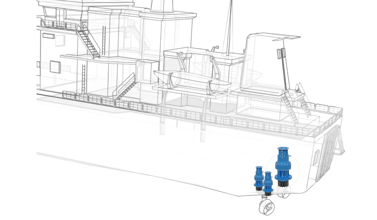
1. Azimuth Thrusters for Ships
Slewing drive planetary gearboxes are integral to azimuth thrusters, enabling precise 360-degree rotation of propulsion units. This enhances vessel maneuverability, dynamic positioning, and thrust vectoring, making them essential for ferries, tugboats, and cargo ships operating in narrow waterways or requiring advanced directional control for docking and navigation.
2. Offshore Oil and Gas Platforms
These slewing gearboxes are widely used in dynamic positioning systems for offshore platforms. They ensure stability by pivoting propulsion units to counteract waves, wind, and currents. The gearbox's durability and resistance to harsh marine environments make it indispensable for maintaining platform positioning during drilling, extraction, or maintenance operations.
3. Harbor and Port Equipment
Slewing drive gearboxes play a critical role in harbor equipment, such as tugboats and pilot boats, where precision maneuvering is vital. They allow vessels to navigate safely in confined port areas, assist larger ships during docking, and perform towing operations, ensuring efficiency and reliability in busy port settings.
4. Wind Turbine Yaw Systems
Used in the yaw drives of wind turbines, these slewing planetary gearboxes enable the rotation of turbine nacelles to optimize wind alignment. Their compact design and high torque output ensure energy efficiency and durability, making them ideal for maintaining consistent power generation in both onshore and offshore wind farms.
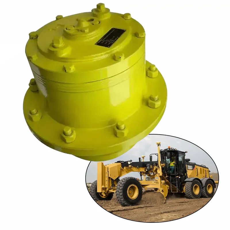
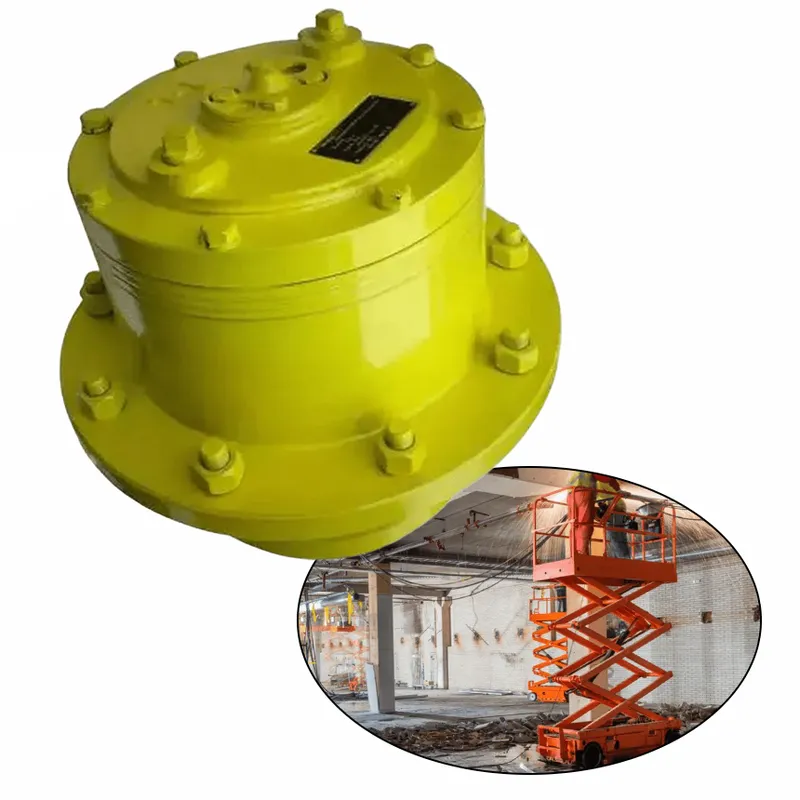
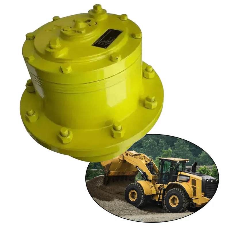
5. Construction and Heavy Machinery
In cranes, excavators, and other heavy equipment, planetary slewing drive gearboxes facilitate smooth rotation of large loads. Their high torque capacity and precise control allow for safe operation in lifting and material handling, ensuring stability and reliability in demanding construction and industrial environments.
 |  |
| Planetary Slewing Drive for Deck Cranes | Planetary Slewing Drive for Concrete Pumps |
 |  |
| Planetary Slewing Drive for Tunnel Boring Machines | Planetary Slewing Drive for Excavators |
Planetary Slewing Gearbox Operation Precautions
- Regular Lubrication Maintenance
Proper lubrication is essential for smooth operation and longevity of a planetary slewing gearbox. Operators must use the manufacturer-recommended grease or oil and follow scheduled lubrication intervals. Insufficient or contaminated lubrication can lead to increased friction, overheating, and accelerated wear of gears, bearings, and seals. - Monitor Load Limits Consistently
Exceeding the specified load capacity can severely damage the gearbox components, such as the sun gear, planet gears, and bearings. Operators should ensure that the applied torque and load remain within the recommended limits to avoid undue stress, misalignment, or failure during operation under heavy-duty conditions. - Inspect Seals and Housing for Damage
The planetary gearbox housing and seals protect internal components from dust, moisture, and corrosion. Regular inspection is necessary to identify cracks, leaks, or seal deterioration. Damaged seals may allow water or contaminants to enter, compromising the gearbox’s performance and reducing its durability in harsh marine or industrial environments. - Avoid Sudden Impact or Shock Loads
Sudden impacts or excessive shock loads can damage the internal gear mechanism, causing misalignment or backlash. Operators should ensure smooth starts and stops during operation and avoid abrupt force applications. Properly designed shock absorbers or dampers can also be used to mitigate such risks. - Monitor Operating Temperatures
Overheating can lead to thermal expansion, material degradation, and failure of critical components. Operators should monitor the operating temperature to ensure it stays within the manufacturer’s specified range. Installing temperature sensors and alarms can help identify overheating issues and prevent long-term damage to the gearbox. - Conduct Routine Inspections and Servicing
Regular inspections of the gearbox for wear, misalignment, or unusual noises are critical for early detection of issues. Scheduled maintenance, including gear alignment checks, bearing replacements, and cleaning, ensures reliable performance and extends the gearbox lifespan. Neglecting routine servicing can result in costly unplanned downtime.

Additional information
| Edited by | Yjx |
|---|