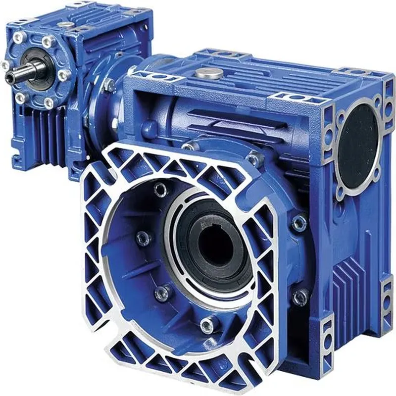
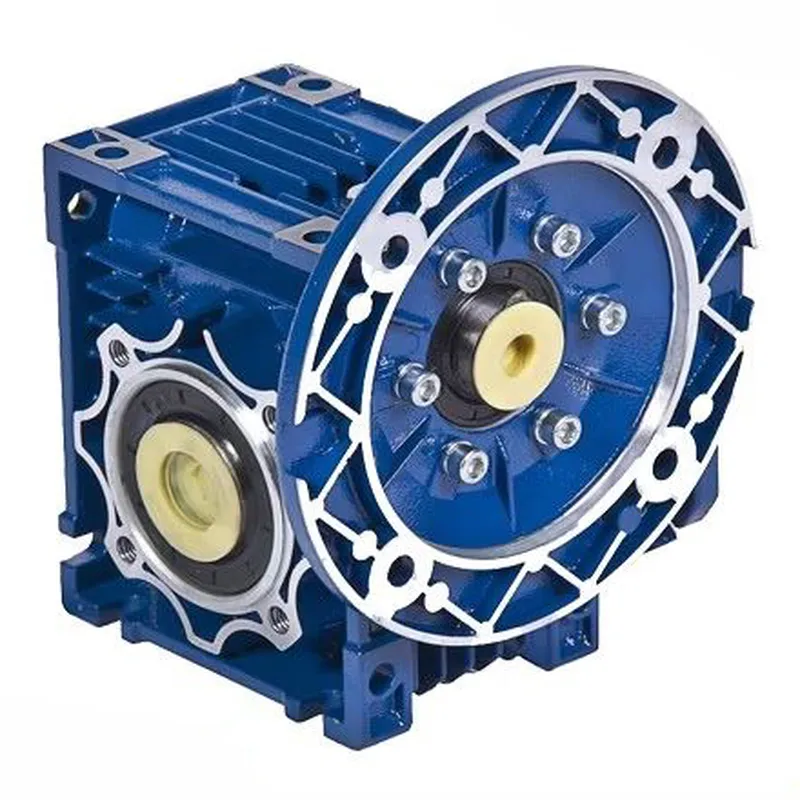
CMN-NMRV130 Worm Gear Reducers/Worm Gearbox
The CMN-NMRV130 worm gear reducer, also known as a worm gearbox, is a robust and versatile mechanical device designed for efficient power transmission in various industrial applications. It features a worm (a screw-like gear) meshing with a worm wheel, providing high torque output with significant speed reduction, typically with gear ratios ranging from 7.5:1 to 100:1. The CMN-NMRV130 model worm gearbox, with its larger center distance of 130mm, is constructed with an aluminum or cast iron housing, ensuring durability and resistance to corrosion.
The CMN-NMRV130 worm gear reducer, also known as a worm gearbox, is a robust and versatile mechanical device designed for efficient power transmission in various industrial applications. It features a worm (a screw-like gear) meshing with a worm wheel, providing high torque output with significant speed reduction, typically with gear ratios ranging from 7.5:1 to 100:1. The CMN-NMRV130 model worm gearbox, with its larger center distance of 130mm, is constructed with an aluminum or cast iron housing, ensuring durability and resistance to corrosion. Its compact, maintenance-free design incorporates synthetic oil for universal mounting positions without lubricant adjustments.
The worm drive gearbox offers self-locking capabilities under certain conditions, making it ideal for applications requiring precise control, such as conveyors, packaging machinery, and robotics. However, due to high backlash (around 1°), it’s unsuitable for high-precision positioning tasks. The CMN-NMRV130 supports motor powers from 1.1kW to 15kW, with input and output options including shafts or flanges, and is known for low noise and vibration.
CMN-NMRV130 Worm Gearbox Specifications
| Type | CMN-NMRV130 Worm Gearbox/ Worm Gear Speed Reducer |
| Model | CMN-NMRV130 |
| Reduction Ratio | 5,7.5,10,15,20,25,30,40,50,60,80,100 |
| Flange | FA / FL or as per your demands |
| Matching Motor | 0.06KW~15KW |
| Material | Die-casting Aluminum Alloy |
| Color | Blue /Silver Grey /Customized |
| Flange Standard | PAM / IEC |
| Accessories | Shaft, Flange, Torque arm, etc |
| Lubricant | Synthetic Oil or Worm Gear Oil |
| Usage | Machinery of food stuff, ceramics, chemicals, packing, dyeing, wood working, glass industries, etc |
| Note: 1) Please choose from the above specifications. 2) If the above options can not meet your demands, please send us your requirements(ratio, flange, mounting, application, or a picture of your old one), and we will recommond a suitable type. | |
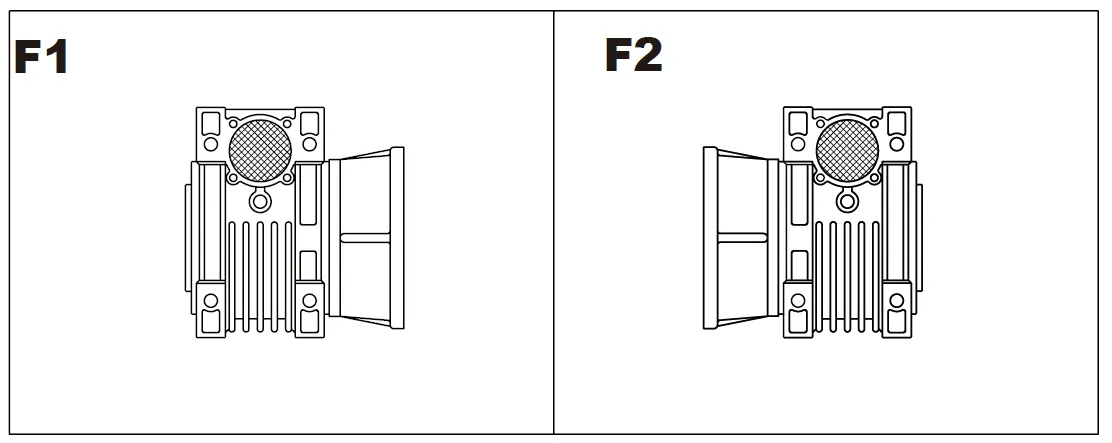
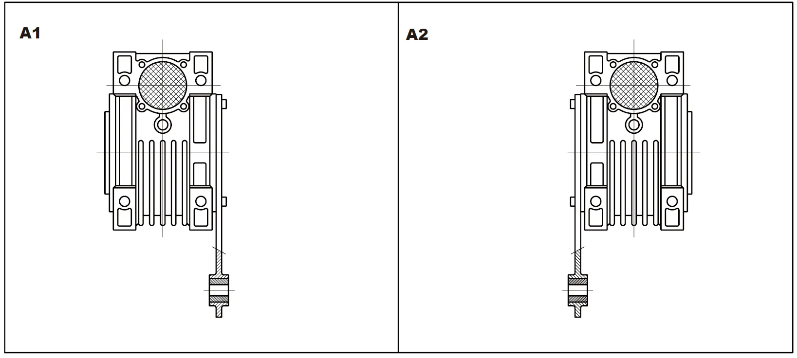
Mounting Position
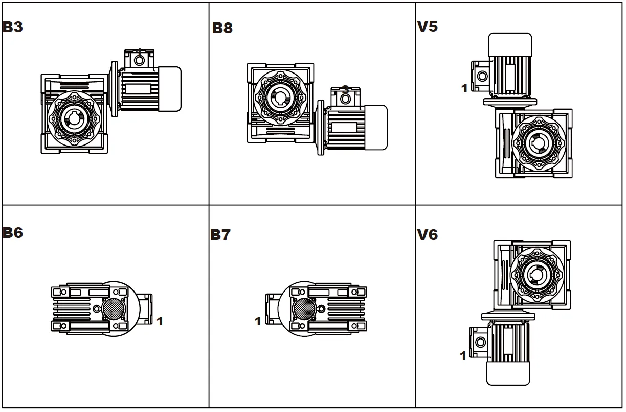
Flange F-FL
Position of Terminal Box
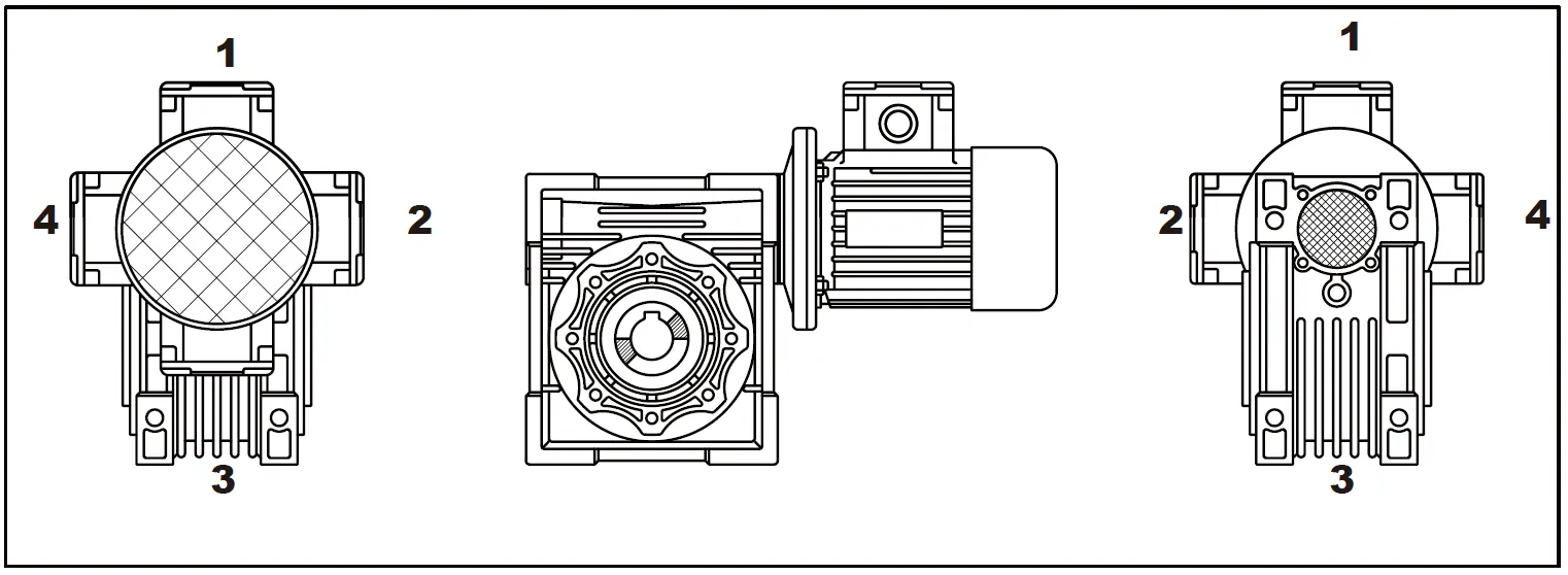
Position of Output Shaft
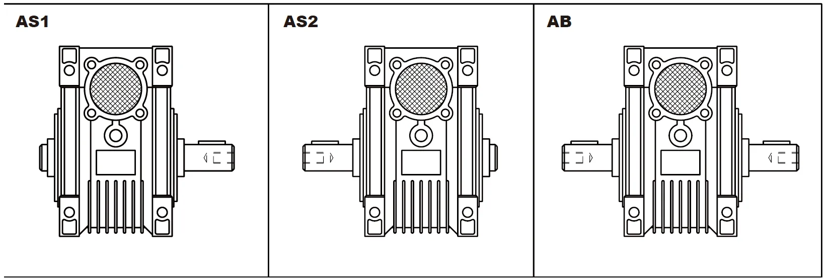
Double Extension Worm Shaft
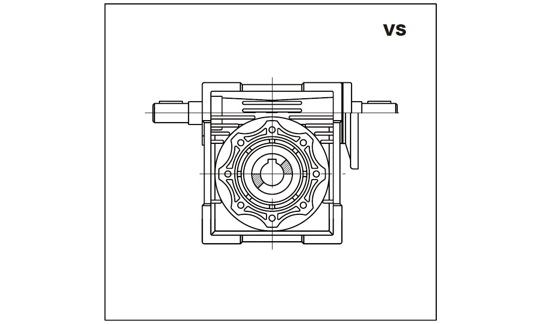
Position of Torque Arm
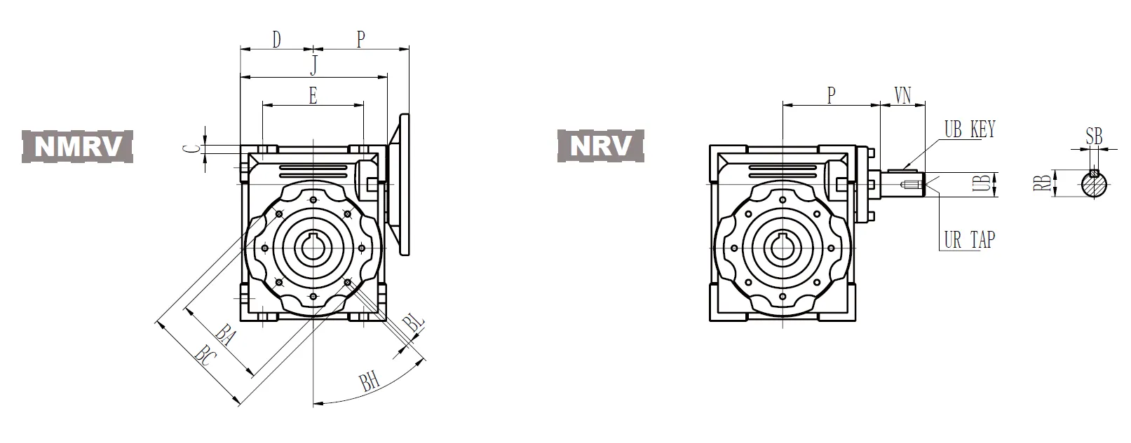
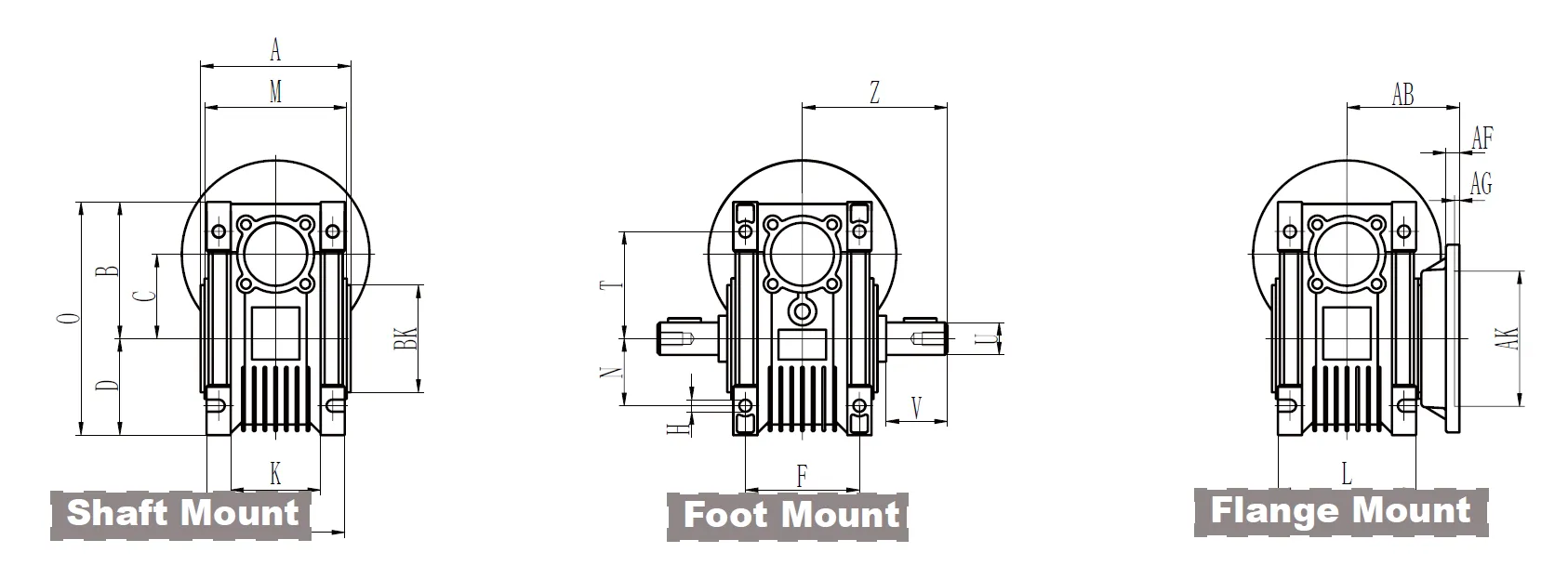
CMN-NMRV130 Worm Gear Reducer Dimensions
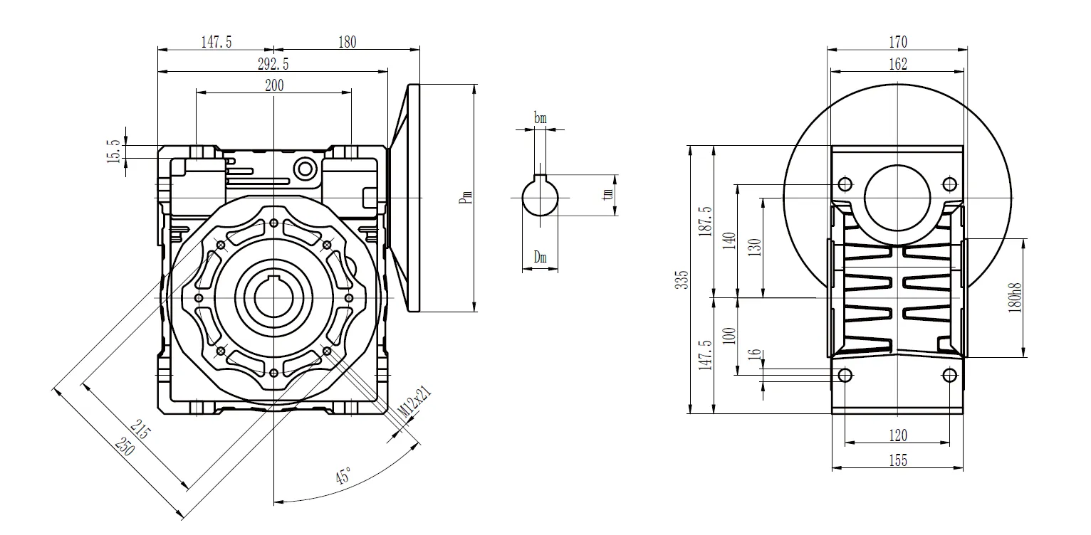
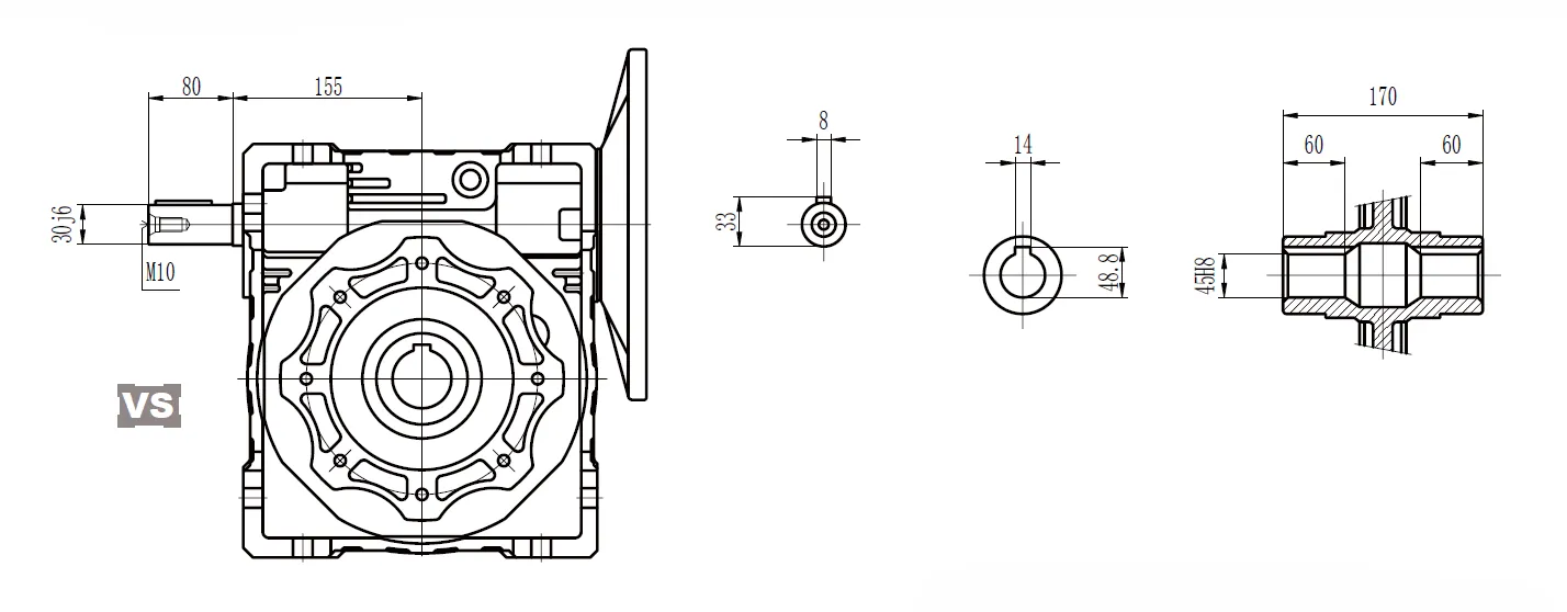
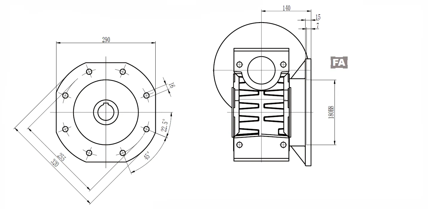
CMN-NMRV Worm Gear Reducer Dimensions
CMN-NMRV Inch Series
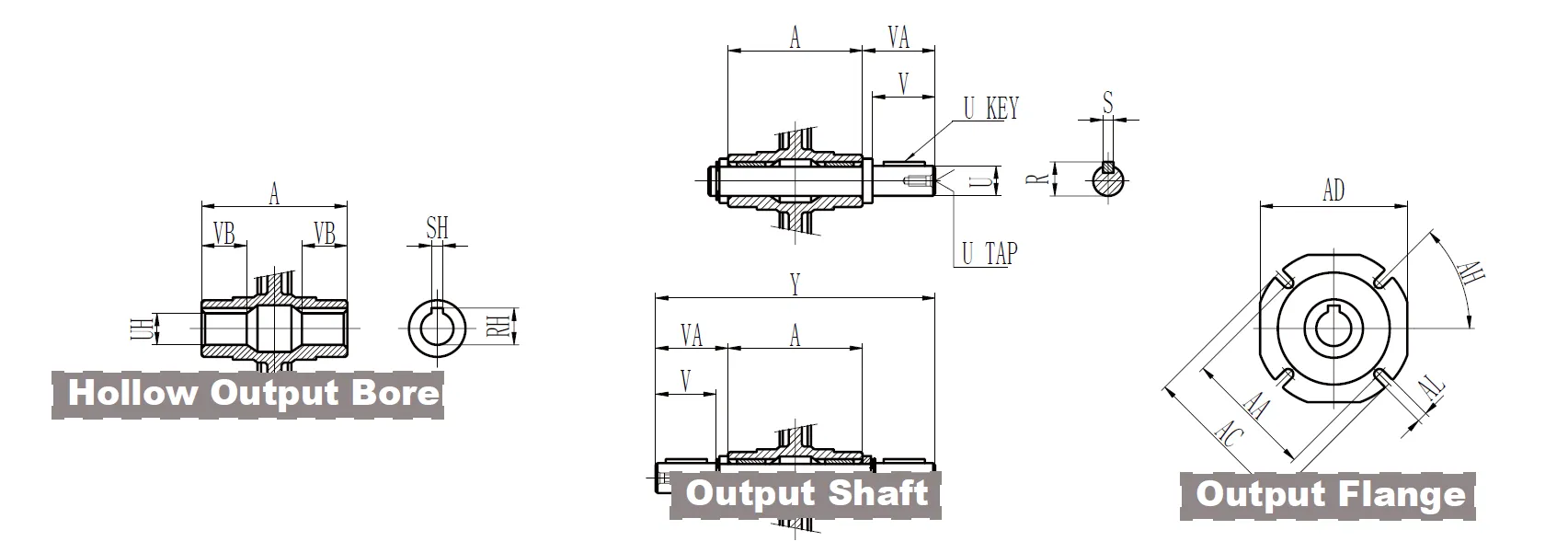
| Hollow Output Bore | 030 | 040 | 050 | 063 | 075 | 090 | 110 | 130 | |
| RH | 0.71 | 0.84 | 1.12 | 1.24 | 1.37 | 1.52 | 1.8 | 1.93 | |
| SH | 0.188 | 0.188 | 0.25 | 0.25 | 0.25 | 0.313 | 0.375 | 0.375 | |
| UH | 0.625+0.001 0 | 0.75+0.001 0 | 1+0.001 0 | 1.125+0.001 0 | 1.25+0.001 0 | 1.375+0.001 0 | 1.625+0.001 0 | 1.750 | |
| VB | 0.83 | 1.14 | 1.28 | 1.42 | 1.56 | 1.77 | 1.97 | 2.24 | |
| Output Shaft | 030 | 040 | 050 | 063 | 075 | 090 | 110 | 130 | |
| R | 0.7 | 0.83 | 1.11 | 1.23 | 1.36 | 1.51 | 1.79 | 1.92 | |
| S | 0.188 | 0.188 | 0.25 | 0.25 | 0.25 | 0.313 | 0.375 | 0.375 | |
| U | 0.6250 -0.0005 | 0.750 -0.0005 | 10 -0.0005 | 0 -0.0005 | 1.250 -0.0005 | 1.3750 -0.0005 | 1.6250 -0.0005 | 1.750 -0.0005 | |
| U KEY | 0.1875x1.125 | 0.1875x1.5 | 0.25x1.5 | 0.25x1.875 | 0.25x2.25 | 0.3125x2.5 | 0.375x2.75 | 0.375x2.75 | |
| UT | 1/4-20 | 1/4-20 | 3/8-16 | 3/8-16 | 1/2-13 | 1/2-13 | 5/8-11 | 5/8-11 | |
| V | 1.57 | 1.97 | 1.97 | 2.36 | 2.76 | 3.15 | 3.54 | 3.54 | |
| VA | 1.67 | 2.09 | 2.11 | 2.5 | 2.89 | 3.33 | 3.72 | 3.74 | |
| Y | 5.82 | 7.25 | 7.84 | 9.41 | 10.5 | 12.17 | 13.54 | 14.17 | |
| CMN-NMRV | 030 | 040 | 050 | 063 | 075 | 090 | 110 | 130 |
| A | 2.48 | 3.07 | 3.62 | 4.41 | 4.72 | 5.51 | 6.1 | 6.69 |
| B | 2.24 | 2.81 | 3.31 | 4.02 | 4.69 | 5.31 | 6.59 | 7.38 |
| BA | 2.56 | 2.95 | 3.35 | 3.74 | 4.53 | 5.12 | 6.5 | 8.46 |
| BC | 2.95 | 3.43 | 3.94 | 4.33 | 5.51 | 6.3 | 7.87 | 9.84 |
| BH | 90 ° | 45 ° | 45 ° | 45 ° | 45 ° | 45 ° | 45° | 45 ° |
| BK | 2.165 0 -0.0018 | 2.362 0 -0.0018 | 2.756 0 -0.0018 | 3.15 0 -0.0021 | 3.74 0 -0.0021 | 4.331 0 -0.0021 | 5.118 0 -0.0025 | 7.087 0 -0.0025 |
| BL | M6x11 | M6x10 | M8x10 | M8x14 | M8x14 | M10x18 | M10x18 | M12x21 |
| C | 1.18 | 1.57 | 1.97 | 2.48 | 2.95 | 3.54 | 4.33 | 5.12 |
| D | 1.57 | 1.97 | 2.36 | 2.83 | 3.39 | 4.06 | 5.02 | 5.81 |
| E | 2.13 | 2.76 | 3.15 | 3.94 | 4.72 | 5.51 | 6.69 | 7.87 |
| F | 1.73 | 2.36 | 2.76 | 3.35 | 3.54 | 3.94 | 4.53 | 4.72 |
| G | 0.22 | 0.26 | 0.28 | 0.31 | 0.39 | 0.43 | 0.57 | 0.61 |
| H | 0.26 | 0.26 | 0.33 | 0.33 | 0.45 | 0.51 | 0.55 | 0.63 |
| J | 3.15 | 3.98 | 4.76 | 5.75 | 6.85 | 8.19 | 9.94 | 11.52 |
| K | 1.26 | 1.69 | 1.93 | 2.64 | 2.83 | 2.91 | - | - |
| L | 2.2 | 2.8 | 3.35 | 4.06 | 4.41 | 5.12 | 5.67 | 6.1 |
| M | 2.28 | 2.87 | 3.43 | 4.17 | 4.49 | 5.28 | 5.83 | 6.38 |
| N | 1.06 | 1.38 | 1.57 | 1.97 | 2.36 | 2.76 | 3.35 | 3.94 |
| O | 3.82 | 4.78 | 5.67 | 6.85 | 8.07 | 9.37 | 11.61 | 13.19 |
| P | 2.64 | 3.15 | 3.54 | 4.13 | 4.96 | 5.63 | 6.81 | 7.6 |
| Q | 0.83 | 2.36 | 2.91 | 3.54 | 4.13 | 4.92 | 5.59 | 6.38 |
| T | 1.73 | 2.17 | 2.52 | 3.15 | 3.66 | 4.02 | 4.92 | 5.51 |
| Z | 2.91 | 3.63 | 3.92 | 4.71 | 5.25 | 6.09 | 6.77 | 7.09 |
| Output Flange | AA | AB | AC | AD | AF | AG | AH | AK | AL | ||
| 030 | FA | 2.68 | 2.15 | 3.15 | 2.76 | 0.24 | 0.16 | 45° | 1.969 | +0.0015 0 | 0.26 |
| 040 | FA | 2.95 | 2.64 | 4.33 | 3.74 | 0.28 | 0.16 | 45° | 2.362 | +0.0018 | 0.35 |
| 0 | |||||||||||
| FB | 2.95 | 3.82 | 4.33 | 3.74 | 0.28 | 0.16 | 45° | 2.362 | +0.0018 0 | 0.35 | |
| FC | 4.53 | 3.15 | 5.51 | - | 0.35 | 0.2 | 45° | 3.74 | +0.0021 0 | 0.37 | |
| FD | 3.94 | 2.28 | 4.72 | - | 0.47 | 0.2 | 45° | 3.15 | +0.0018 | 0.35 | |
| 0 | |||||||||||
| 050 | FA | 3.35 | 3.54 | 4.92 | 4.33 | 0.35 | 0.2 | 45° | 2.756 | +0.0018 | 0.43 |
| 0 | |||||||||||
| FB | 3.35 | 4.72 | 4.92 | 4.33 | 0.35 | 0.2 | 45° | 2.756 | +0.0018 0 | 0.43 | |
| FC | 5.12 | 3.5 | 6.3 | - | 0.39 | 0.2 | 45° | 4.331 | +0.0021 0 | 0.37 | |
| FD | 4.53 | 2.83 | 5.51 | - | 0.57 | 0.2 | 45° | 3.543 | +0.0021 | 0.43 | |
| 0 | |||||||||||
| 063 | FA | 4.13 | 3.23 | 7.09 | 5.59 | 0.39 | 0.24 | 45° | 4.528 | +0.0021 | 0.43 |
| 0 | |||||||||||
| FB | 5.91 | 4.41 | 7.09 | 5.59 | 0.39 | 0.24 | 45° | 4.528 | +0.0021 | 0.43 | |
| 0 | |||||||||||
| FC | 6.5 | 3.86 | 7.87 | - | 0.39 | 0.2 | 45° | 5.118 | +0.0025 0 | 0.43 | |
| FD | 6.5 | 4.21 | 7.87 | - | 0.39 | 0.2 | 45° | 5.118 | +0.0025 | 0.43 | |
| 0 | |||||||||||
| FE | 5.12 | 3.17 | 6.3 | - | 0.65 | 0.2 | 45° | 4.331 | +0.0021 | 0.43 | |
| 0 | |||||||||||
| 075 | FA | 6.5 | 4.37 | 7.87 | 6.69 | 0.51 | 0.24 | 45° | 5.118 | +0.0025 | 0.55 |
| 0 | |||||||||||
| FB | 5.12 | 3.54 | 6.3 | - | 0.51 | 0.24 | 45° | 4.331 | +0.0021 | 0.55 | |
| 0 | |||||||||||
| 090 | FA | 6.89 | 4.37 | 8.27 | 8.27 | 0.51 | 0.24 | 45° | 5.984 | +0.0025 | 0.55 |
| 0 | |||||||||||
| FB | 8.46 | 4.8 | 9.84 | - | 0.71 | 0.24 | 45° | 7.087 | +0.0025 0 | 0.55 | |
| FC | 6.5 | 4.33 | 7.87 | - | 0.67 | 0.24 | 45° | 5.118 | +0.0025 0 | 0.43 | |
| FD | 6.89 | 5.94 | 8.27 | - | 0.51 | 0.24 | 45° | 5.984 | +0.0025 | 0.55 | |
| 0 | |||||||||||
| 110 | FA | 9.06 | 5.16 | 11.02 | 10.24 | 0.59 | 0.24 | 45° | 6.693 | +0.0025 | 0.55 |
| 0 | |||||||||||
| FB | 9.06 | 7.09 | 11.02 | 10.24 | 0.59 | 0.24 | 45° | 6.693 | +0.0025 | 0.55 | |
| 0 | |||||||||||
| 130 | FA | 10.04 | 5.51 | 12.6 | 11.42 | 0.59 | 0.24 | 22.5° | 7.087 | +0.0025 0 | 0.63 |
| Input Shaft | 030 | 040 | 050 | 063 | 075 | 090 | 110 | 130 | |
| SB | 0.094 | 0.125 | 0.188 | 0.188 | 0.188 | 0.188 | 0.25 | 0.25 | |
| RB | 0.42 | 0.55 | 0.7 | 0.83 | 0.96 | 0.96 | 1.24 | 1.36 | |
| UB | 0.3750 -0.0005 | 0.50 -0.0005 | 0.6250 -0.0005 | 0.750 -0.0005 | 0.8750 -0.0005 | 0.8750 -0.0005 | 1.1250 -0.0005 | 1.250 -0.0005 | |
| UB KEY | 0.094x0.875 | 0.125x0.875 | 0.1875x1.125 | 0.1875x1.5 | 0.1875x1.875 | 0.1875x1.875 | 0.25x2.25 | 0.25x2.5 | |
| UR | - | 1/4-20 | 1/4-20 | 1/4-20 | 1/4-20 | 1/4-20 | 3/8-16 | 1/2-13 | |
| VN | 1.18 | 1.18 | 1.58 | 1.97 | 2.36 | 2.36 | 2.76 | 3.15 | |
High Speed Extension Shaft Dimensions
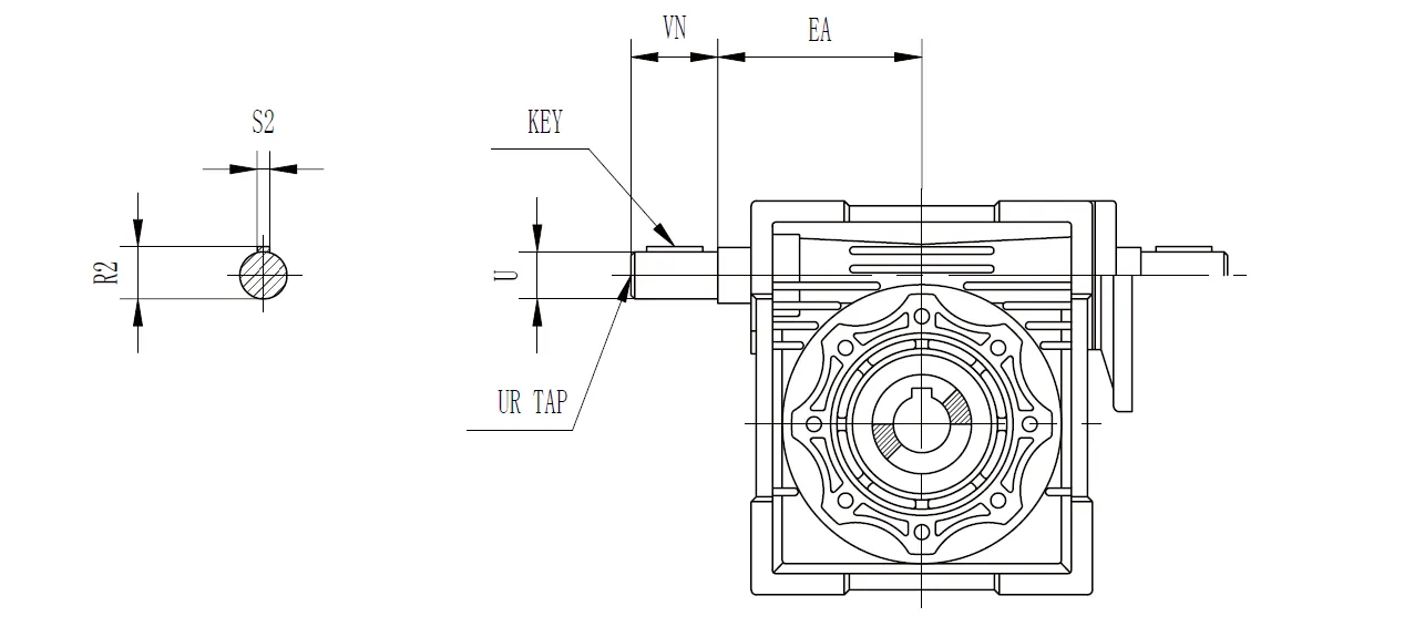
| CMN-NMRV | EA | U | VN | UR | S2 | R2 | KEY | |
| Length | Square | |||||||
| 030 | 1.772 | 0.3750 -0.0005 | 1.18 | - | 0.093 | 0.42 | 0.875 | 0.094 |
| 040 | 2.087 | 0.50 -0.0005 | 1.18 | 1/4-20 | 0.13 | 0.55 | 0.875 | 0.125 |
| 050 | 2.52 | 0.6250 -0.0005 | 1.58 | 1/4-20 | 0.19 | 0.7 | 1.125 | 0.188 |
| 063 | 2.953 | 0.750 -0.0005 | 1.97 | 1/4-20 | 0.19 | 0.83 | 1.5 | 0.188 |
| 075 | 3.543 | 0.8750 -0.0005 | 2.36 | 1/4-20 | 0.19 | 0.96 | 1.875 | 0.188 |
| 090 | 4.252 | 0.8750 -0.0005 | 2.36 | 1/4-20 | 0.19 | 0.96 | 1.875 | 0.188 |
| 110 | 5.315 | 1.1250 -0.0005 | 2.76 | 3/8-16 | 0.25 | 1.24 | 2.25 | 0.25 |
| 130 | 6.102 | 1.250 -0.0005 | 3.15 | 1/2-13 | 0.25 | 1.36 | 2.5 | 0.25 |
Torque Arm Dimensions
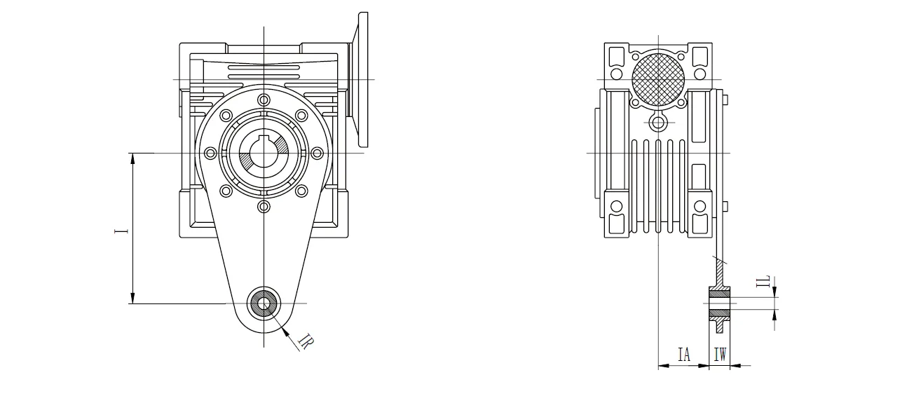
| CMN-NMRV | I | IA | IL | IR | IW |
| 025 | 2.76 | 0.69 | 0.31 | 0.59 | 0.55 |
| 030 | 3.35 | 0.94 | 0.31 | 0.59 | 0.55 |
| 040 | 3.94 | 1.24 | 0.39 | 0.71 | 0.55 |
| 050 | 3.94 | 1.52 | 0.39 | 0.71 | 0.55 |
| 063 | 5.91 | 1.93 | 0.39 | 0.71 | 0.55 |
| 075 | 7.87 | 1.87 | 0.79 | 1.18 | 0.98 |
| 090 | 7.87 | 2.26 | 0.79 | 1.18 | 0.98 |
| 110 | 9.84 | 2.44 | 0.98 | 1.38 | 1.18 |
| 130 | 9.84 | 2.72 | 0.98 | 1.38 | 1.18 |
Protective Cover Dimensions
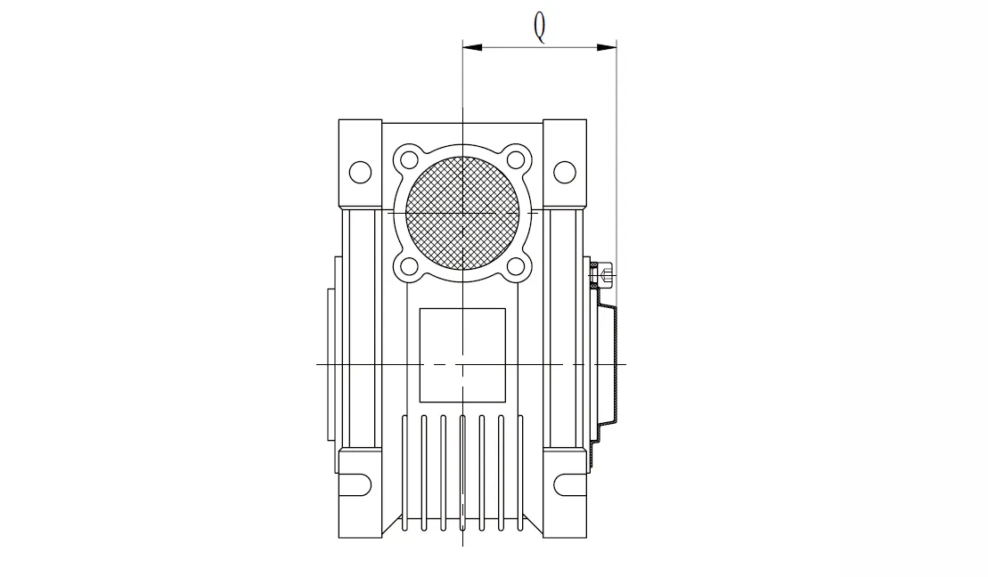
| CMN-NMRV | Q |
| 030 | 1.65 |
| 040 | 1.97 |
| 050 | 2.28 |
| 063 | 2.72 |
| 075 | 2.91 |
| 090 | 3.39 |
| 110 | 3.7 |
| 130 | 4.02 |
NEMA Flange Availability
| CMN-NMRV | NEMA Flange | Input Bore Diameter | Available Ratios | |||||||||||
| 5 | 7.5 | 10 | 15 | 20 | 25 | 30 | 40 | 50 | 60 | 80 | 100 | |||
| 030 | 48C | 0.5 | ● | ● | ● | ● | ● | ● | ● | ● | ● | ● | ● | |
| 040 | 56C | 0.625 | ● | ● | ● | ● | ● | ● | ● | ● | ● | ● | ● | ● |
| 050 | 56C | 0.625 | ● | ● | ● | ● | ● | ● | ● | ● | ● | ● | ● | ● |
| 063 | 56C | 0.625 | ● | ● | ● | ● | ● | ● | ● | ● | ||||
| 140TC | 0.875 | ● | ● | ● | ● | ● | ● | ● | ||||||
| 075 | 56C | 0.625 | ● | ● | ● | ● | ||||||||
| 140TC | 0.875 | ● | ● | ● | ● | ● | ● | |||||||
| 180TC | 1.125 | ● | ● | ● | ||||||||||
| 090 | 56C | 0.625 | ● | ● | ||||||||||
| 140TC | 0.875 | ● | ● | ● | ● | ● | ||||||||
| 180TC | 1.125 | ● | ● | ● | ● | ● | ● | ● | ||||||
| 110 | 140TC | 0.875 | ● | ● | ● | ● | ||||||||
| 180TC | 1.125 | ● | ● | ● | ● | ● | ● | |||||||
| 210TC | 1.375 | ● | ● | ● | ● | |||||||||
| 130 | 140TC | 0.875 | ● | ● | ||||||||||
| 180TC | 1.125 | ● | ● | ● | ● | ● | ||||||||
| 210TC | 1.375 | ● | ● | ● | ● | ● | ● | ● | ||||||
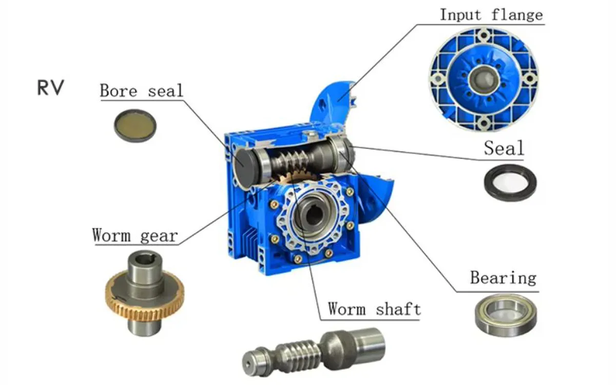
CMN-NMRV130 Worm Gearbox Parts Structure
- Worm Shaft
The worm shaft is a cylindrical, screw-like component made of hardened steel or alloy, designed to engage the worm wheel. It transmits rotational motion with high precision, ensuring efficient torque transfer. Its robust construction withstands heavy loads, offering durability in demanding industrial environments. - Worm Gear
The worm gear, typically crafted from bronze or phosphor bronze, meshes with the worm shaft to achieve significant speed reduction. Its toothed design ensures smooth power transmission. The material choice enhances wear resistance, making it suitable for continuous operation in high-torque applications. - Housing
The gearbox housing is constructed from aluminum or cast iron, providing structural integrity and corrosion resistance. Its compact design protects internal components from dust and debris. The housing supports universal mounting, allowing flexible installation in various orientations for diverse industrial setups. - Bearings
High-quality bearings support the worm shaft and wheel, reducing friction and ensuring smooth operation. They are designed to handle axial and radial loads, enhancing worm reducer gearbox longevity. Precision bearings minimize vibration, contributing to the NMRV130’s low-noise performance in demanding applications. - Seals
Oil seals, typically made of nitrile rubber or Viton, prevent lubricant leakage and protect against contaminants. These seals ensure the worm drive gearbox remains maintenance-free by maintaining proper lubrication. Their robust design withstands high temperatures and harsh conditions, extending the gearbox’s operational life. - Output Shaft
The output shaft, made of hardened steel, delivers the reduced speed and high torque to the driven equipment. It supports various configurations, such as single or double output, and can be fitted with flanges or couplings for versatile integration into machinery systems. - Input Flange
The input flange, typically made of aluminum or cast iron, connects the worm reduction gearbox to the motor. It ensures precise alignment and secure mounting, accommodating various motor sizes. Its robust design supports high torque transmission, enhancing the gearbox’s compatibility with diverse industrial applications.
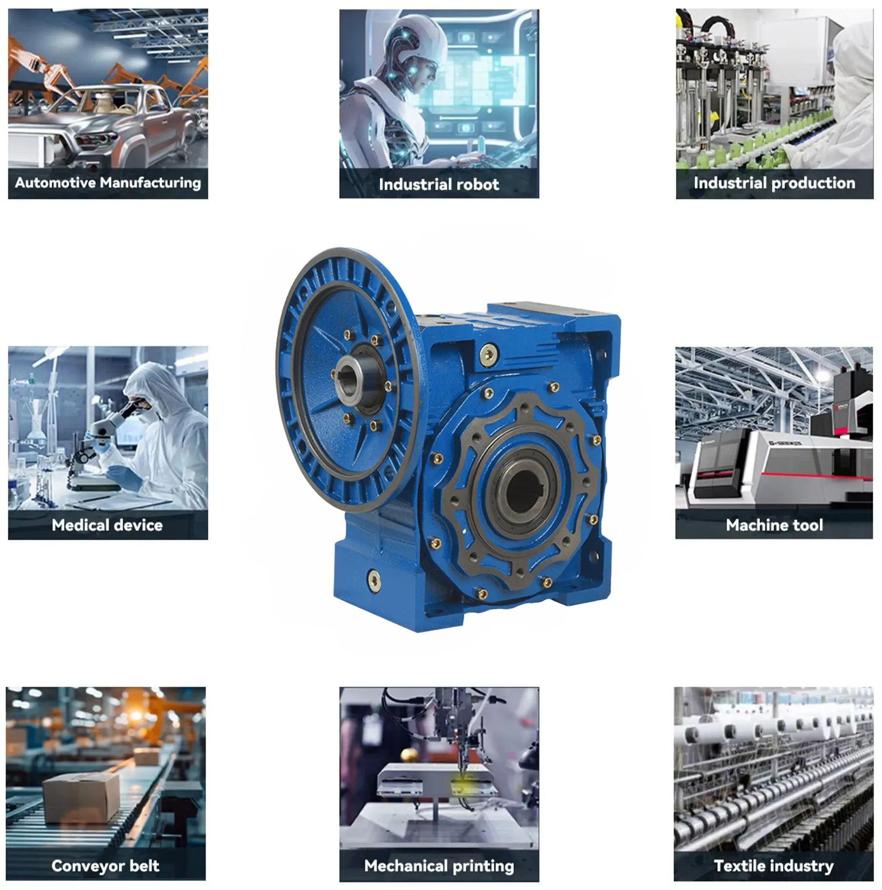
CMN-NMRV130 Worm Gear Reducer Applications
- Conveyor Systems
The CMN-NMRV130 worm gear reducer is widely used in conveyor systems for material handling in industries like mining and manufacturing. Its high torque and speed reduction ensure smooth, controlled movement of heavy loads, enhancing efficiency and reliability in continuous transport operations. - Packaging Machinery
In packaging machinery, the worm gear speed reducer provides precise speed control for processes like filling, sealing, and labeling. Its compact design and high torque output enable consistent performance in automated systems, ensuring accuracy and reducing downtime in high-speed production lines for consumer goods. - Robotics
The CMN-NMRV130 worm drive gearbox is employed in robotic systems for precise motion control in industrial automation. Its self-locking feature and high torque make it ideal for robotic arms, enabling accurate positioning and stable operation in tasks like assembly, welding, and material handling. - Textile Machinery
Textile production relies on the worm gear gearbox for driving looms, spinning machines, and winding equipment. Its smooth operation and low noise enhance precision in fabric production, while the durable design ensures reliable performance under continuous operation in demanding textile manufacturing environments. - Food Processing Equipment
In food processing, the CMN-NMRV130 worm reducer gearbox drives mixers, slicers, and conveyors with hygienic, maintenance-free operation. Its corrosion-resistant housing and synthetic oil lubrication ensure compliance with food safety standards, providing reliable torque for consistent performance in processing and packaging lines. - Hoisting Equipment
The worm drive reduction gearbox is used in hoisting equipment like cranes and winches, delivering high torque for lifting heavy loads. Its self-locking capability ensures safety by preventing load slippage, while the robust construction supports reliable operation in construction and industrial lifting applications.
Worm Reducer Gearbox Troubleshooting
- Excessive Noise or Vibration
If the worm gearbox produces unusual noise or vibration, check for misaligned shafts or loose mounting bolts. Inspect the worm and wheel for wear or damage. Ensure proper lubrication with synthetic oil, as low levels can cause friction, leading to noise in operation. - Overheating
Overheating may result from overloading or insufficient lubrication. Verify the load does not exceed the worm reducer gearbox’s rated capacity. Check oil levels and quality, replacing if degraded. Ensure proper ventilation around the gearbox to dissipate heat, preventing damage to internal components during continuous use. - Oil Leakage
Oil leaks often stem from worn or damaged seals. Inspect seals around the input and output shafts for cracks or wear. Replace faulty seals with compatible materials like nitrile rubber. Ensure the vent plug is functional to prevent pressure buildup, which can force oil out. - Reduced Torque Output
If torque output drops, inspect the worm and wheel for excessive wear or tooth damage. Check for improper input speed or motor misalignment. Verify the gear ratio matches the application requirements. Lubrication issues can also reduce efficiency, so ensure proper oil levels. - Shaft Seizure or Stiffness
Shaft seizure may occur due to contamination or inadequate lubrication. Examine the worm drive gearbox for debris or water ingress. Flush and replace the oil if contaminated. Inspect bearings for damage, replacing them if worn to restore smooth operation and prevent further issues. - Failure to Self-Lock
If the self-locking feature fails, check the worm gear angle and condition, as wear can reduce locking efficiency. Verify the gear ratio, as high ratios enhance self-locking. Inspect for excessive load or improper mounting, which can compromise the gearbox’s locking mechanism.
Additional information
| Edited by | Yjx |
|---|