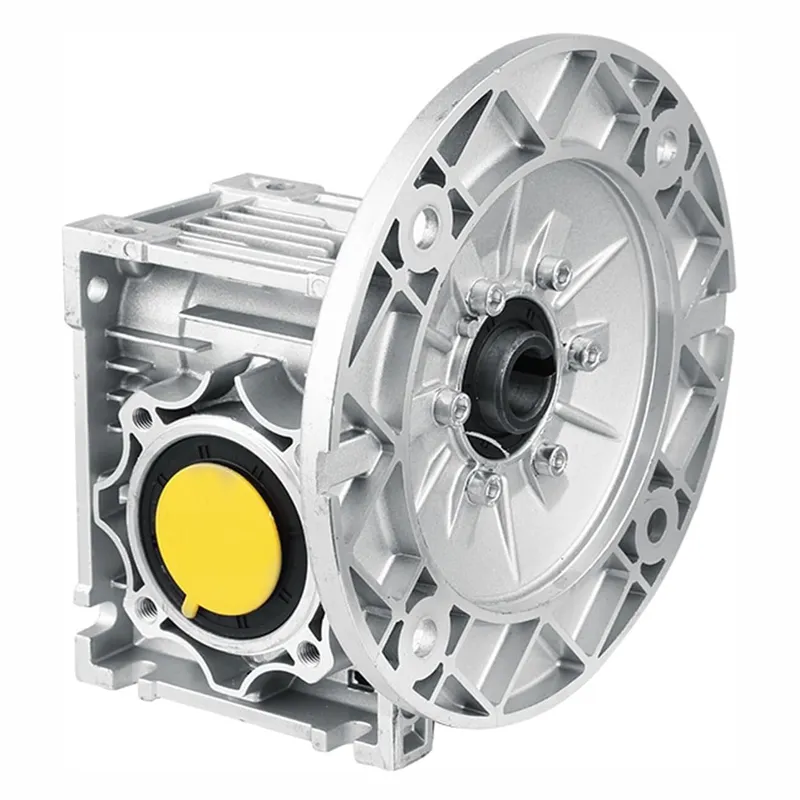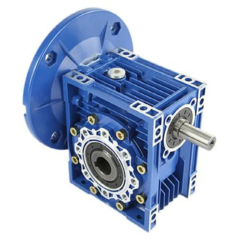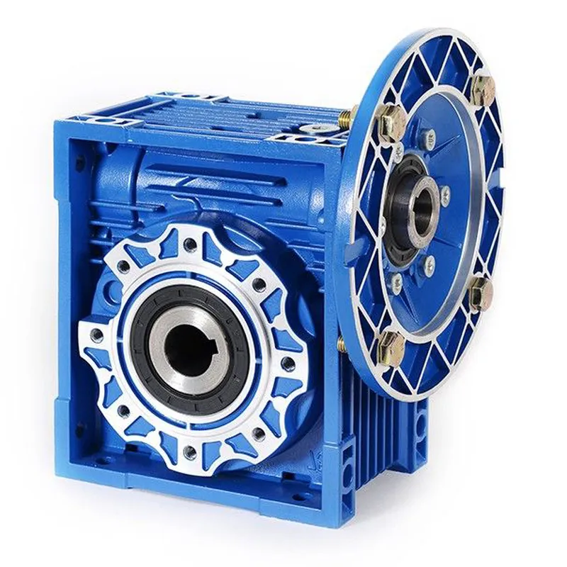
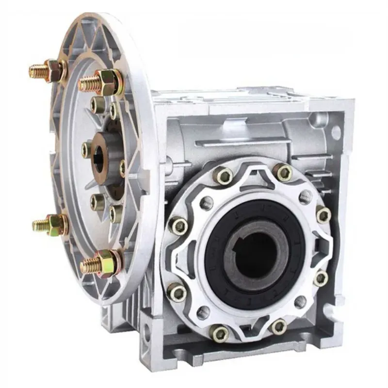
CMN-NMRV090 Worm Gear Reducers/Worm Gearbox
The CMN-NMRV090 worm gear reducer, often referred to as a worm gearbox, is a type of mechanical transmission device designed to transmit torque and motion between non-parallel shafts, typically at a right angle. This specific model, CMN-NMRV090, is part of the CMN-NMRV series worm gearbox, renowned for its compact design, versatility, and high efficiency. It incorporates a worm gear set, which consists of a worm (the driving gear) and a worm wheel (the driven gear), allowing for significant speed reduction and torque multiplication in a single stage.
The CMN-NMRV090 worm gear reducer, often referred to as a worm gearbox, is a type of mechanical transmission device designed to transmit torque and motion between non-parallel shafts, typically at a right angle. This specific model, CMN-NMRV090, is part of the CMN-NMRV series worm gearbox, renowned for its compact design, versatility, and high efficiency. It incorporates a worm gear set, which consists of a worm (the driving gear) and a worm wheel (the driven gear), allowing for significant speed reduction and torque multiplication in a single stage.
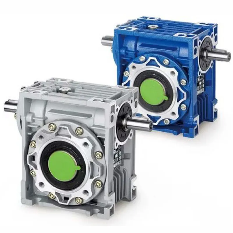
The CMN-NMRV090 worm reducer gearbox is widely used in industrial machinery, conveyors, automation systems, and packaging equipment due to its lightweight aluminum housing, corrosion resistance, and ability to operate quietly. The worm drive gearbox offers a range of gear ratios, high load capacity, long service life, and low maintenance requirements. Its modular design allows for easy integration with electric motors, making it an ideal solution for compact and reliable power transmission in various applications.
CMN-NMRV090 Worm Gearbox Specifications
| Type | CMN-NMRV090 Worm Gearbox/ Worm Gear Speed Reducer |
| Model | CMN-NMRV090 |
| Reduction Ratio | 5,7.5,10,15,20,25,30,40,50,60,80,100 |
| Flange | FA / FL or as per your demands |
| Matching Motor | 0.06KW~15KW |
| Material | Die-casting Aluminum Alloy |
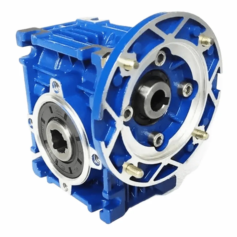
| Color | Blue /Silver Grey /Customized |
| Flange Standard | PAM / IEC |
| Accessories | Shaft, Flange, Torque arm, etc |
| Lubricant | Synthetic Oil or Worm Gear Oil |
| Usage | Machinery of food stuff, ceramics, chemicals, packing, dyeing, wood working, glass industries, etc |
| Note: 1) Please choose from the above specifications. 2) If the above options can not meet your demands, please send us your requirements(ratio, flange, mounting, application, or a picture of your old one), and we will recommond a suitable type. | |
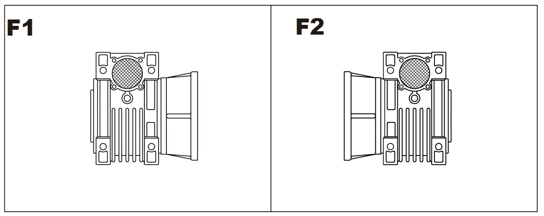
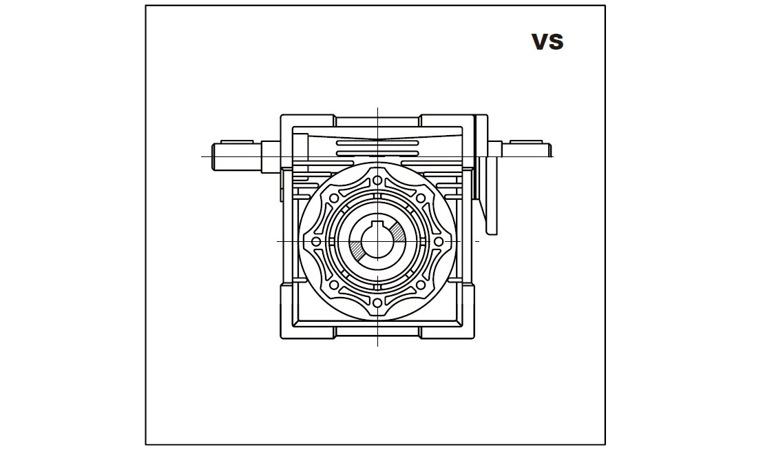
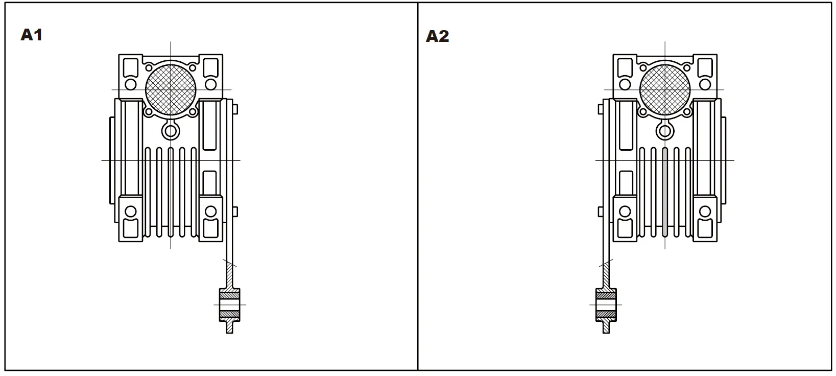
Mounting Position
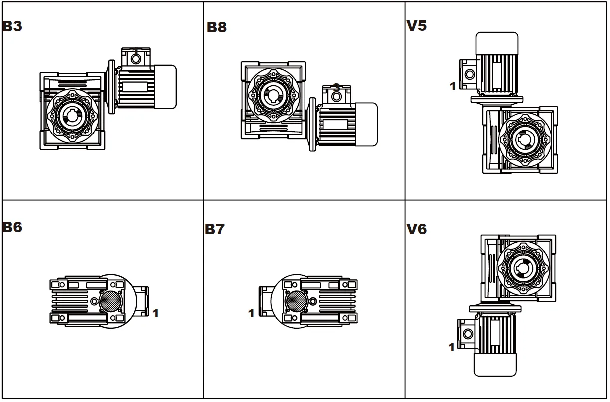
Flange F-FL
Position of Terminal Box
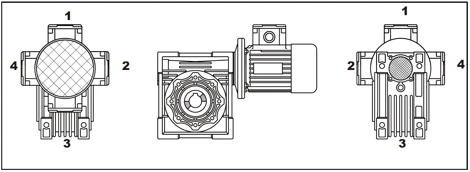
Position of Output Shaft
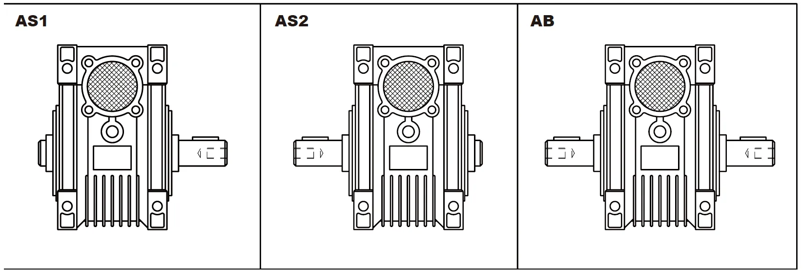
Double Extension Worm Shaft
Position of Torque Arm
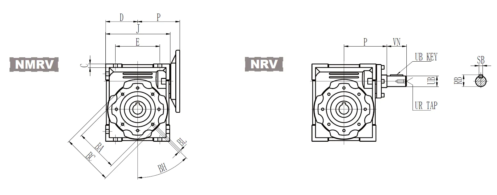
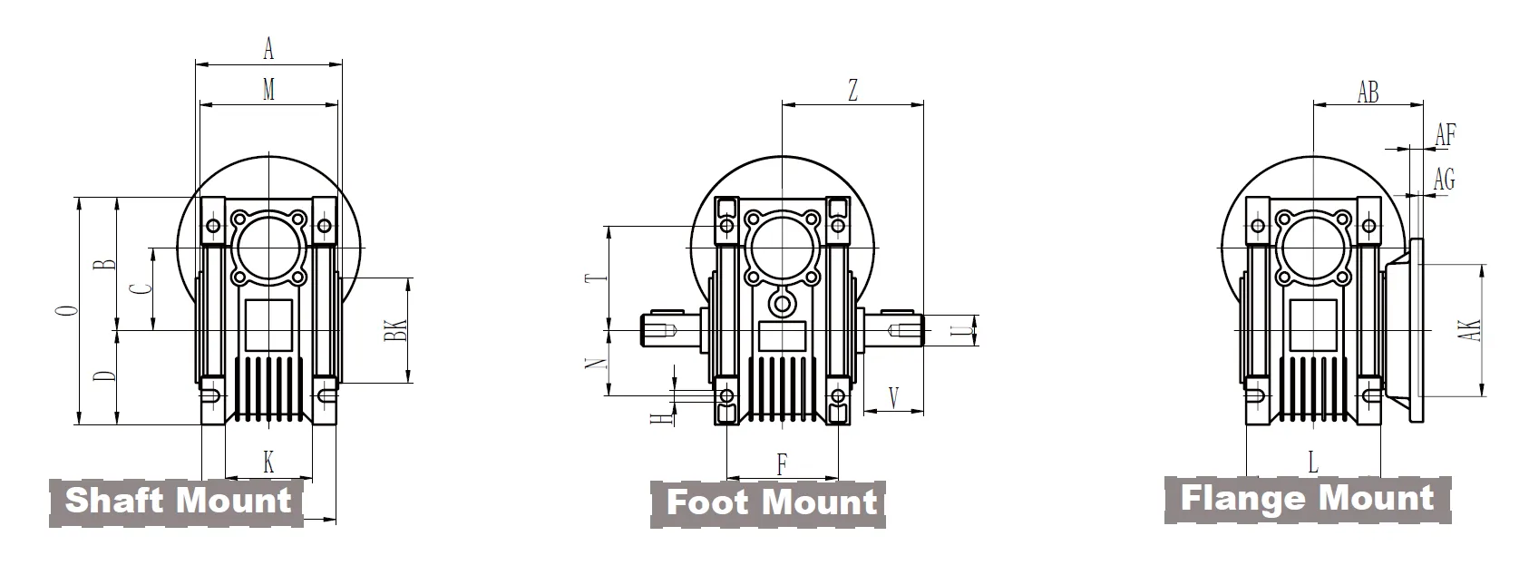
CMN-NMRV090 Worm Gear Reducer Dimensions
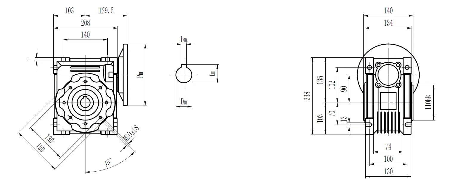
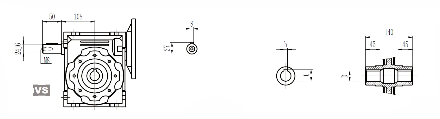
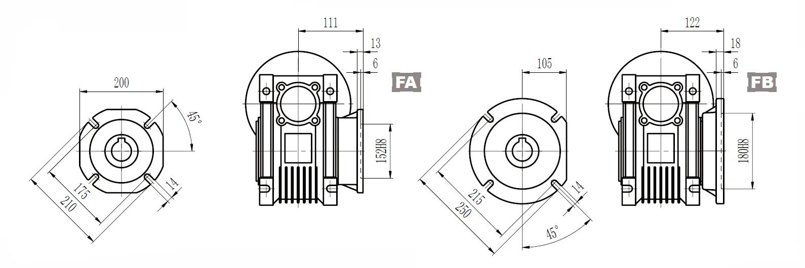
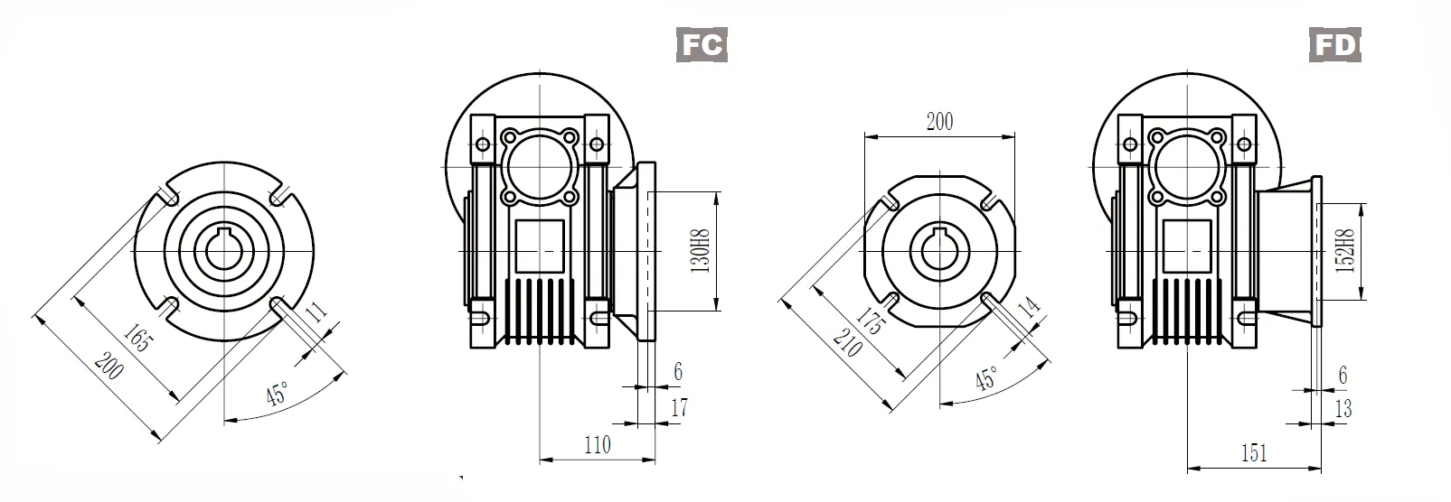
CMN-NMRV Worm Gear Reducer Dimensions
CMN-NMRV Inch Series
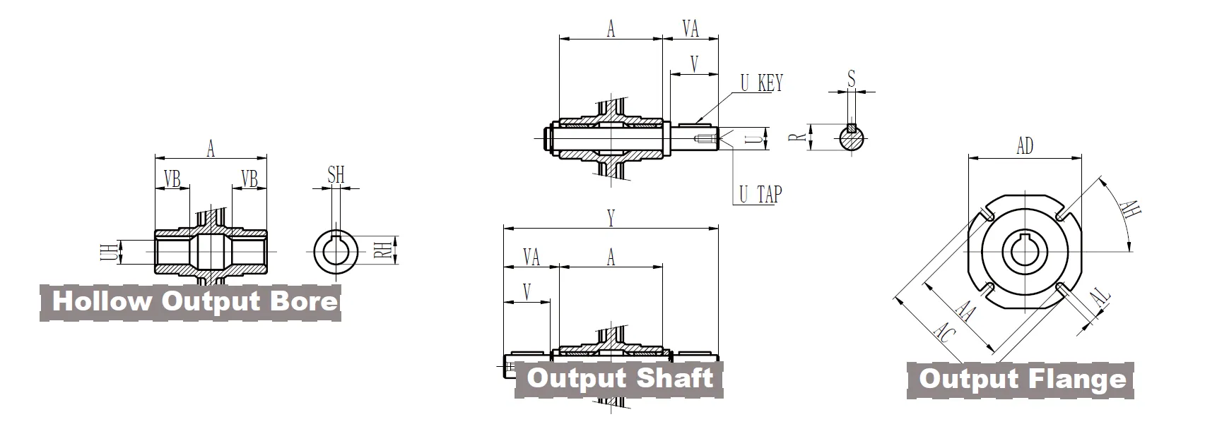
| Hollow Output Bore | 030 | 040 | 050 | 063 | 075 | 090 | 110 | 130 | |
| RH | 0.71 | 0.84 | 1.12 | 1.24 | 1.37 | 1.52 | 1.8 | 1.93 | |
| SH | 0.188 | 0.188 | 0.25 | 0.25 | 0.25 | 0.313 | 0.375 | 0.375 | |
| UH | 0.625+0.001 0 | 0.75+0.001 0 | 1+0.001 0 | 1.125+0.001 0 | 1.25+0.001 0 | 1.375+0.001 0 | 1.625+0.001 0 | 1.750 | |
| VB | 0.83 | 1.14 | 1.28 | 1.42 | 1.56 | 1.77 | 1.97 | 2.24 | |
| Output Shaft | 030 | 040 | 050 | 063 | 075 | 090 | 110 | 130 | |
| R | 0.7 | 0.83 | 1.11 | 1.23 | 1.36 | 1.51 | 1.79 | 1.92 | |
| S | 0.188 | 0.188 | 0.25 | 0.25 | 0.25 | 0.313 | 0.375 | 0.375 | |
| U | 0.6250 -0.0005 | 0.750 -0.0005 | 10 -0.0005 | 0 -0.0005 | 1.250 -0.0005 | 1.3750 -0.0005 | 1.6250 -0.0005 | 1.750 -0.0005 | |
| U KEY | 0.1875x1.125 | 0.1875x1.5 | 0.25x1.5 | 0.25x1.875 | 0.25x2.25 | 0.3125x2.5 | 0.375x2.75 | 0.375x2.75 | |
| UT | 1/4-20 | 1/4-20 | 3/8-16 | 3/8-16 | 1/2-13 | 1/2-13 | 5/8-11 | 5/8-11 | |
| V | 1.57 | 1.97 | 1.97 | 2.36 | 2.76 | 3.15 | 3.54 | 3.54 | |
| VA | 1.67 | 2.09 | 2.11 | 2.5 | 2.89 | 3.33 | 3.72 | 3.74 | |
| Y | 5.82 | 7.25 | 7.84 | 9.41 | 10.5 | 12.17 | 13.54 | 14.17 | |
| CMN-NMRV | 030 | 040 | 050 | 063 | 075 | 090 | 110 | 130 |
| A | 2.48 | 3.07 | 3.62 | 4.41 | 4.72 | 5.51 | 6.1 | 6.69 |
| B | 2.24 | 2.81 | 3.31 | 4.02 | 4.69 | 5.31 | 6.59 | 7.38 |
| BA | 2.56 | 2.95 | 3.35 | 3.74 | 4.53 | 5.12 | 6.5 | 8.46 |
| BC | 2.95 | 3.43 | 3.94 | 4.33 | 5.51 | 6.3 | 7.87 | 9.84 |
| BH | 90 ° | 45 ° | 45 ° | 45 ° | 45 ° | 45 ° | 45° | 45 ° |
| BK | 2.165 0 -0.0018 | 2.362 0 -0.0018 | 2.756 0 -0.0018 | 3.15 0 -0.0021 | 3.74 0 -0.0021 | 4.331 0 -0.0021 | 5.118 0 -0.0025 | 7.087 0 -0.0025 |
| BL | M6x11 | M6x10 | M8x10 | M8x14 | M8x14 | M10x18 | M10x18 | M12x21 |
| C | 1.18 | 1.57 | 1.97 | 2.48 | 2.95 | 3.54 | 4.33 | 5.12 |
| D | 1.57 | 1.97 | 2.36 | 2.83 | 3.39 | 4.06 | 5.02 | 5.81 |
| E | 2.13 | 2.76 | 3.15 | 3.94 | 4.72 | 5.51 | 6.69 | 7.87 |
| F | 1.73 | 2.36 | 2.76 | 3.35 | 3.54 | 3.94 | 4.53 | 4.72 |
| G | 0.22 | 0.26 | 0.28 | 0.31 | 0.39 | 0.43 | 0.57 | 0.61 |
| H | 0.26 | 0.26 | 0.33 | 0.33 | 0.45 | 0.51 | 0.55 | 0.63 |
| J | 3.15 | 3.98 | 4.76 | 5.75 | 6.85 | 8.19 | 9.94 | 11.52 |
| K | 1.26 | 1.69 | 1.93 | 2.64 | 2.83 | 2.91 | - | - |
| L | 2.2 | 2.8 | 3.35 | 4.06 | 4.41 | 5.12 | 5.67 | 6.1 |
| M | 2.28 | 2.87 | 3.43 | 4.17 | 4.49 | 5.28 | 5.83 | 6.38 |
| N | 1.06 | 1.38 | 1.57 | 1.97 | 2.36 | 2.76 | 3.35 | 3.94 |
| O | 3.82 | 4.78 | 5.67 | 6.85 | 8.07 | 9.37 | 11.61 | 13.19 |
| P | 2.64 | 3.15 | 3.54 | 4.13 | 4.96 | 5.63 | 6.81 | 7.6 |
| Q | 0.83 | 2.36 | 2.91 | 3.54 | 4.13 | 4.92 | 5.59 | 6.38 |
| T | 1.73 | 2.17 | 2.52 | 3.15 | 3.66 | 4.02 | 4.92 | 5.51 |
| Z | 2.91 | 3.63 | 3.92 | 4.71 | 5.25 | 6.09 | 6.77 | 7.09 |
| Output Flange | AA | AB | AC | AD | AF | AG | AH | AK | AL | ||
| 030 | FA | 2.68 | 2.15 | 3.15 | 2.76 | 0.24 | 0.16 | 45° | 1.969 | +0.0015 0 | 0.26 |
| 040 | FA | 2.95 | 2.64 | 4.33 | 3.74 | 0.28 | 0.16 | 45° | 2.362 | +0.0018 | 0.35 |
| 0 | |||||||||||
| FB | 2.95 | 3.82 | 4.33 | 3.74 | 0.28 | 0.16 | 45° | 2.362 | +0.0018 0 | 0.35 | |
| FC | 4.53 | 3.15 | 5.51 | - | 0.35 | 0.2 | 45° | 3.74 | +0.0021 0 | 0.37 | |
| FD | 3.94 | 2.28 | 4.72 | - | 0.47 | 0.2 | 45° | 3.15 | +0.0018 | 0.35 | |
| 0 | |||||||||||
| 050 | FA | 3.35 | 3.54 | 4.92 | 4.33 | 0.35 | 0.2 | 45° | 2.756 | +0.0018 | 0.43 |
| 0 | |||||||||||
| FB | 3.35 | 4.72 | 4.92 | 4.33 | 0.35 | 0.2 | 45° | 2.756 | +0.0018 0 | 0.43 | |
| FC | 5.12 | 3.5 | 6.3 | - | 0.39 | 0.2 | 45° | 4.331 | +0.0021 0 | 0.37 | |
| FD | 4.53 | 2.83 | 5.51 | - | 0.57 | 0.2 | 45° | 3.543 | +0.0021 | 0.43 | |
| 0 | |||||||||||
| 063 | FA | 4.13 | 3.23 | 7.09 | 5.59 | 0.39 | 0.24 | 45° | 4.528 | +0.0021 | 0.43 |
| 0 | |||||||||||
| FB | 5.91 | 4.41 | 7.09 | 5.59 | 0.39 | 0.24 | 45° | 4.528 | +0.0021 | 0.43 | |
| 0 | |||||||||||
| FC | 6.5 | 3.86 | 7.87 | - | 0.39 | 0.2 | 45° | 5.118 | +0.0025 0 | 0.43 | |
| FD | 6.5 | 4.21 | 7.87 | - | 0.39 | 0.2 | 45° | 5.118 | +0.0025 | 0.43 | |
| 0 | |||||||||||
| FE | 5.12 | 3.17 | 6.3 | - | 0.65 | 0.2 | 45° | 4.331 | +0.0021 | 0.43 | |
| 0 | |||||||||||
| 075 | FA | 6.5 | 4.37 | 7.87 | 6.69 | 0.51 | 0.24 | 45° | 5.118 | +0.0025 | 0.55 |
| 0 | |||||||||||
| FB | 5.12 | 3.54 | 6.3 | - | 0.51 | 0.24 | 45° | 4.331 | +0.0021 | 0.55 | |
| 0 | |||||||||||
| 090 | FA | 6.89 | 4.37 | 8.27 | 8.27 | 0.51 | 0.24 | 45° | 5.984 | +0.0025 | 0.55 |
| 0 | |||||||||||
| FB | 8.46 | 4.8 | 9.84 | - | 0.71 | 0.24 | 45° | 7.087 | +0.0025 0 | 0.55 | |
| FC | 6.5 | 4.33 | 7.87 | - | 0.67 | 0.24 | 45° | 5.118 | +0.0025 0 | 0.43 | |
| FD | 6.89 | 5.94 | 8.27 | - | 0.51 | 0.24 | 45° | 5.984 | +0.0025 | 0.55 | |
| 0 | |||||||||||
| 110 | FA | 9.06 | 5.16 | 11.02 | 10.24 | 0.59 | 0.24 | 45° | 6.693 | +0.0025 | 0.55 |
| 0 | |||||||||||
| FB | 9.06 | 7.09 | 11.02 | 10.24 | 0.59 | 0.24 | 45° | 6.693 | +0.0025 | 0.55 | |
| 0 | |||||||||||
| 130 | FA | 10.04 | 5.51 | 12.6 | 11.42 | 0.59 | 0.24 | 22.5° | 7.087 | +0.0025 0 | 0.63 |
| Input Shaft | 030 | 040 | 050 | 063 | 075 | 090 | 110 | 130 | |
| SB | 0.094 | 0.125 | 0.188 | 0.188 | 0.188 | 0.188 | 0.25 | 0.25 | |
| RB | 0.42 | 0.55 | 0.7 | 0.83 | 0.96 | 0.96 | 1.24 | 1.36 | |
| UB | 0.3750 -0.0005 | 0.50 -0.0005 | 0.6250 -0.0005 | 0.750 -0.0005 | 0.8750 -0.0005 | 0.8750 -0.0005 | 1.1250 -0.0005 | 1.250 -0.0005 | |
| UB KEY | 0.094x0.875 | 0.125x0.875 | 0.1875x1.125 | 0.1875x1.5 | 0.1875x1.875 | 0.1875x1.875 | 0.25x2.25 | 0.25x2.5 | |
| UR | - | 1/4-20 | 1/4-20 | 1/4-20 | 1/4-20 | 1/4-20 | 3/8-16 | 1/2-13 | |
| VN | 1.18 | 1.18 | 1.58 | 1.97 | 2.36 | 2.36 | 2.76 | 3.15 | |
High Speed Extension Shaft Dimensions
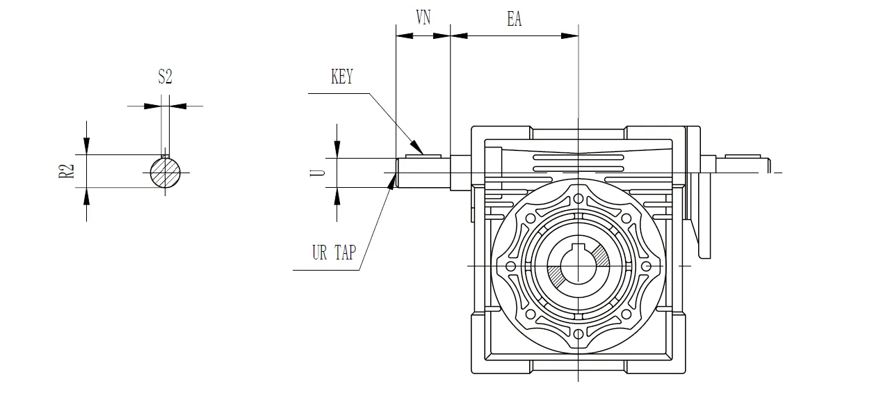
| CMN-NMRV | EA | U | VN | UR | S2 | R2 | KEY | |
| Length | Square | |||||||
| 030 | 1.772 | 0.3750 -0.0005 | 1.18 | - | 0.093 | 0.42 | 0.875 | 0.094 |
| 040 | 2.087 | 0.50 -0.0005 | 1.18 | 1/4-20 | 0.13 | 0.55 | 0.875 | 0.125 |
| 050 | 2.52 | 0.6250 -0.0005 | 1.58 | 1/4-20 | 0.19 | 0.7 | 1.125 | 0.188 |
| 063 | 2.953 | 0.750 -0.0005 | 1.97 | 1/4-20 | 0.19 | 0.83 | 1.5 | 0.188 |
| 075 | 3.543 | 0.8750 -0.0005 | 2.36 | 1/4-20 | 0.19 | 0.96 | 1.875 | 0.188 |
| 090 | 4.252 | 0.8750 -0.0005 | 2.36 | 1/4-20 | 0.19 | 0.96 | 1.875 | 0.188 |
| 110 | 5.315 | 1.1250 -0.0005 | 2.76 | 3/8-16 | 0.25 | 1.24 | 2.25 | 0.25 |
| 130 | 6.102 | 1.250 -0.0005 | 3.15 | 1/2-13 | 0.25 | 1.36 | 2.5 | 0.25 |
Torque Arm Dimensions
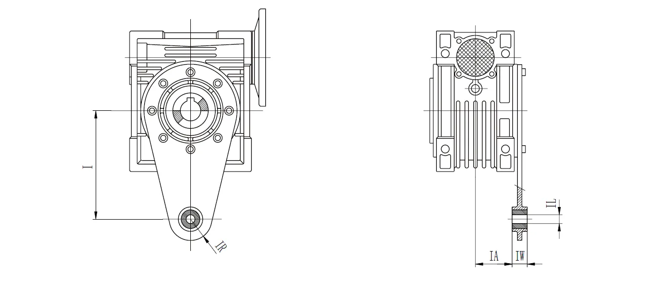
| CMN-NMRV | I | IA | IL | IR | IW |
| 025 | 2.76 | 0.69 | 0.31 | 0.59 | 0.55 |
| 030 | 3.35 | 0.94 | 0.31 | 0.59 | 0.55 |
| 040 | 3.94 | 1.24 | 0.39 | 0.71 | 0.55 |
| 050 | 3.94 | 1.52 | 0.39 | 0.71 | 0.55 |
| 063 | 5.91 | 1.93 | 0.39 | 0.71 | 0.55 |
| 075 | 7.87 | 1.87 | 0.79 | 1.18 | 0.98 |
| 090 | 7.87 | 2.26 | 0.79 | 1.18 | 0.98 |
| 110 | 9.84 | 2.44 | 0.98 | 1.38 | 1.18 |
| 130 | 9.84 | 2.72 | 0.98 | 1.38 | 1.18 |
Protective Cover Dimensions
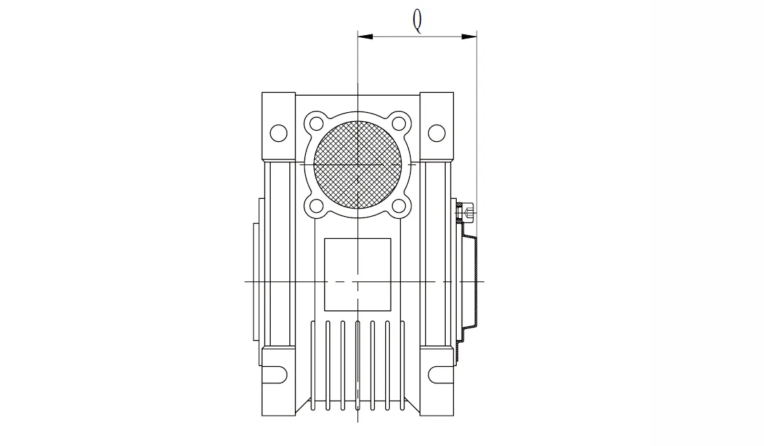
| CMN-NMRV | Q |
| 030 | 1.65 |
| 040 | 1.97 |
| 050 | 2.28 |
| 063 | 2.72 |
| 075 | 2.91 |
| 090 | 3.39 |
| 110 | 3.7 |
| 130 | 4.02 |
NEMA Flange Availability
| CMN-NMRV | NEMA Flange | Input Bore Diameter | Available Ratios | |||||||||||
| 5 | 7.5 | 10 | 15 | 20 | 25 | 30 | 40 | 50 | 60 | 80 | 100 | |||
| 030 | 48C | 0.5 | ● | ● | ● | ● | ● | ● | ● | ● | ● | ● | ● | |
| 040 | 56C | 0.625 | ● | ● | ● | ● | ● | ● | ● | ● | ● | ● | ● | ● |
| 050 | 56C | 0.625 | ● | ● | ● | ● | ● | ● | ● | ● | ● | ● | ● | ● |
| 063 | 56C | 0.625 | ● | ● | ● | ● | ● | ● | ● | ● | ||||
| 140TC | 0.875 | ● | ● | ● | ● | ● | ● | ● | ||||||
| 075 | 56C | 0.625 | ● | ● | ● | ● | ||||||||
| 140TC | 0.875 | ● | ● | ● | ● | ● | ● | |||||||
| 180TC | 1.125 | ● | ● | ● | ||||||||||
| 090 | 56C | 0.625 | ● | ● | ||||||||||
| 140TC | 0.875 | ● | ● | ● | ● | ● | ||||||||
| 180TC | 1.125 | ● | ● | ● | ● | ● | ● | ● | ||||||
| 110 | 140TC | 0.875 | ● | ● | ● | ● | ||||||||
| 180TC | 1.125 | ● | ● | ● | ● | ● | ● | |||||||
| 210TC | 1.375 | ● | ● | ● | ● | |||||||||
| 130 | 140TC | 0.875 | ● | ● | ||||||||||
| 180TC | 1.125 | ● | ● | ● | ● | ● | ||||||||
| 210TC | 1.375 | ● | ● | ● | ● | ● | ● | ● | ||||||
CMN-NMRV090 Worm Reducer Gearbox Advantages
1. High Torque Output and Efficiency
The CMN-NMRV090 worm gearbox delivers exceptional torque for heavy-duty applications, with gear ratios from 7.5:1 to 100:1. Its efficient design ensures optimal power transmission, minimizing energy loss while maintaining consistent performance in demanding industrial environments like conveyors and robotics.
2. Compact and Lightweight Design
Constructed with a durable yet lightweight aluminum alloy or cast iron housing, the CMN-NMRV090 worm gear reducers offer a compact footprint. This design facilitates easy integration into space-constrained systems, enhancing versatility for applications in food processing, packaging, and textile machinery without sacrificing strength.
3. Self-Locking Capability
The worm gear mechanism provides inherent self-locking under specific conditions, preventing back-driving. This feature ensures safety and stability in applications requiring precise positioning, such as hoists or elevators, by holding loads securely without additional braking systems, reducing overall system complexity.
4. Low Noise and Smooth Operation
Precision-engineered worm and wheel components, typically made from bronze and nodular cast iron, ensure smooth, quiet operation. The CMN-NMRV090 worm gear speed reducer minimizes vibrations and noise, making it ideal for noise-sensitive environments like medical equipment or automated production lines, enhancing workplace comfort.
5. Low Maintenance and Durability
Filled with synthetic oil and featuring a sealed housing, the worm drive gearbox requires minimal maintenance. Its robust construction resists wear and corrosion, ensuring long service life in harsh conditions, such as chemical plants or outdoor machinery, reducing downtime and operational costs.
6. Universal Mounting Flexibility
The CMN-NMRV090 worm gear gearbox’s versatile design supports multiple mounting configurations, including flange and foot options. This adaptability simplifies installation across diverse applications, from material handling to agricultural equipment, allowing seamless integration into existing systems while accommodating various spatial and operational requirements.
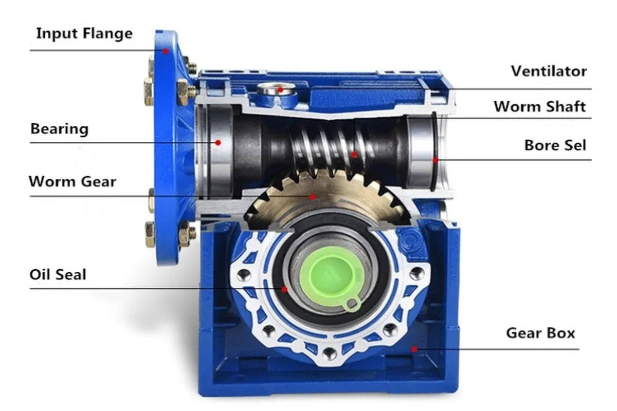
Worm Gear Speed Reducer Components
Worm Shaft
The worm shaft is the driving component of the gearbox, typically made of hardened steel for durability. It transmits rotational motion from the motor and features spiral threads that engage with the worm wheel to generate torque and speed reduction.
Worm Gear
The worm gear, often made of bronze or other wear-resistant materials, is the driven component that meshes with the worm shaft. It acts as the output gear, providing smooth torque transmission and ensuring the desired speed reduction ratio.
Gear Housing
The gear housing encloses and protects the internal components from external elements like dust, moisture, and impact. It is typically crafted from materials like aluminum or cast iron, offering strength, corrosion resistance, and structural support for long-term operation.
Bearings
Bearings support the worm shaft and worm wheel, ensuring smooth and stable rotation under load. High-quality bearings reduce friction, enhance operational efficiency, and contribute to the gearbox’s durability by minimizing wear on internal components during continuous operation.
Oil Seals
Oil seals prevent lubricant leakage and block contaminants like dust and debris from entering the gearbox. They maintain consistent lubrication of internal components, reducing friction and wear while extending the overall lifespan of the speed reducer.
Lubrication System
The lubrication system, often using oil or grease, ensures that the worm shaft and worm wheel maintain smooth engagement. Proper lubrication minimizes friction, reduces heat generation, and enhances the efficiency and durability of the worm gear reducer.
Input Shaft and Flange
The input shaft connects the motor to the gearbox, transmitting motion into the worm shaft. The flange facilitates secure attachment of motors or other driving devices, ensuring proper alignment and efficient power transfer into the gearbox system.
Output Shaft
The output shaft delivers the reduced speed and amplified torque to the connected machinery or load. It is designed to handle high torque levels and is often equipped with features like keyways or splines for secure coupling with external components.
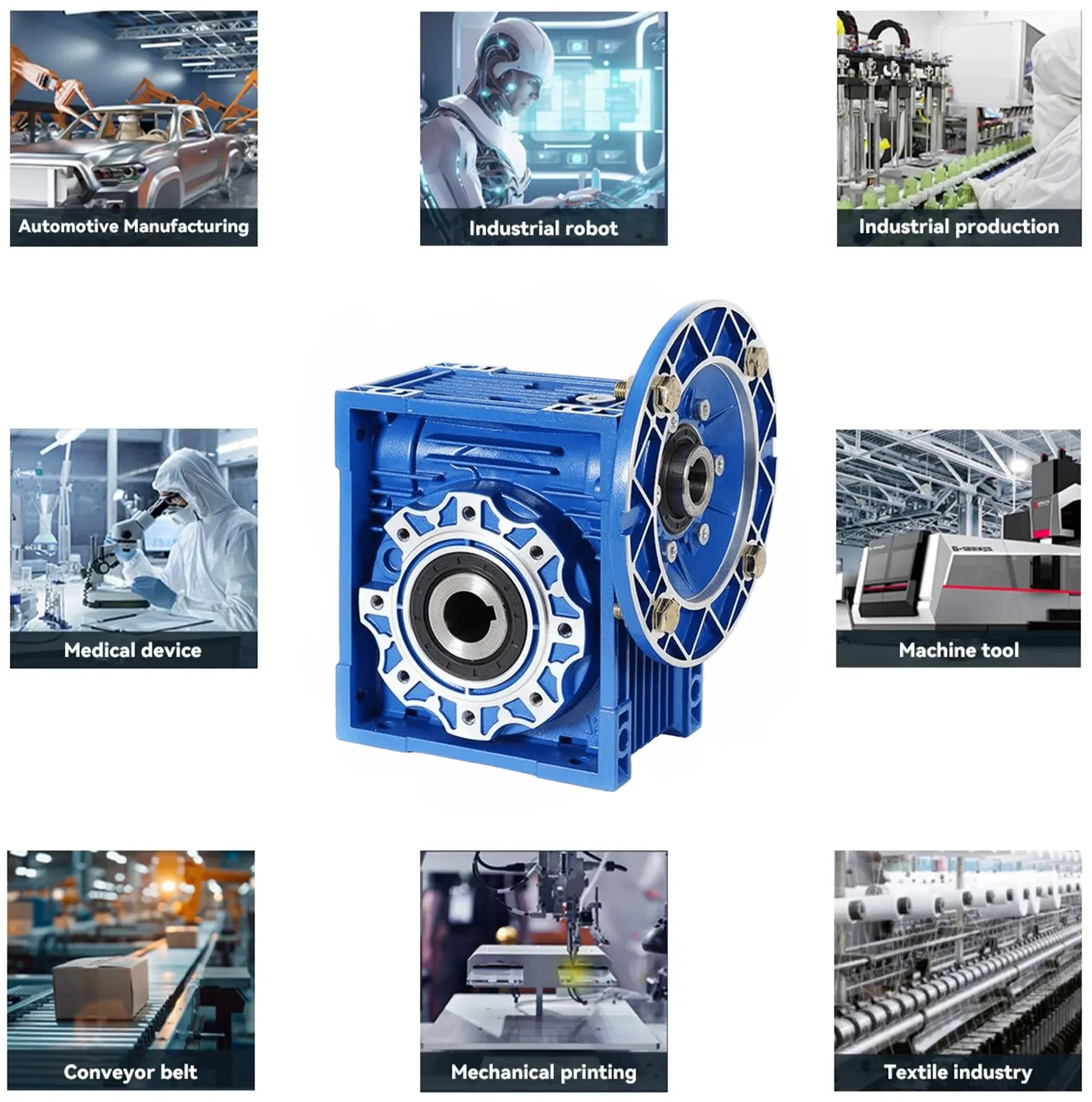
CMN-NMRV090 Worm Drive Gearbox Applications
1. Food Processing Industry
CMN-NMRV090 worm gearboxes are widely used in food processing for conveyors, mixers, and packaging machines. Their compact design and low noise ensure hygienic, efficient operation. The self-locking feature enhances safety, preventing unintended movement in equipment handling delicate or heavy food products.
2. Textile Industry: In textile manufacturing, right angle worm gearboxes drive looms, spinning machines, and dyeing equipment. Their high torque and precise speed control ensure consistent fabric production. The durable housing resists wear in dusty environments, while universal mounting allows seamless integration into complex textile machinery setups.
3. Material Handling Industry
CMN-NMRV090 worm gear speed reducers power conveyor belts, hoists, and automated sorting systems in material handling. Their robust construction and self-locking capability ensure reliable load management. The compact design fits tight spaces, enhancing efficiency in warehouses, logistics centers, and distribution facilities with heavy-duty operations.
4. Robotics and Automation
The aluminum worm gearbox is ideal for robotics, driving articulated arms and automated guided vehicles. Its high torque and precision enable accurate movements. The low-maintenance design and quiet operation suit cleanroom environments, ensuring reliable performance in automated assembly lines or precision manufacturing.
5. Agricultural Machinery
In agriculture, CMN-NMRV090 worm reducer gearboxes are used in harvesters, irrigation systems, and feed mixers. Their corrosion-resistant housing withstands harsh outdoor conditions. The high torque output supports heavy loads, while low maintenance ensures continuous operation during critical farming seasons, enhancing productivity.
6. Chemical and Pharmaceutical Industry
Worm drive reduction gearboxes drive mixers, pumps, and agitators in chemical and pharmaceutical production. Their sealed, low-maintenance design prevents contamination and ensures reliability in corrosive environments. The smooth operation and precise control are critical for maintaining consistent processes in sensitive manufacturing applications.
Additional information
| Edited by | Yjx |
|---|