CMN-NMRV040 Przekładnie ślimakowe/przekładnie ślimakowe
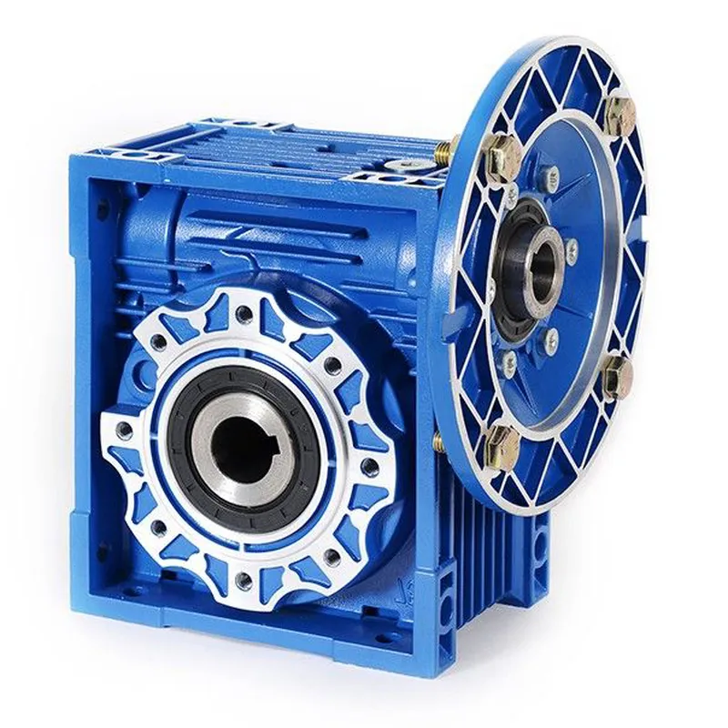
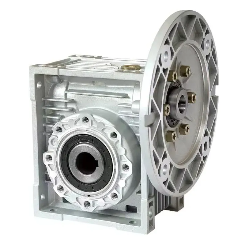
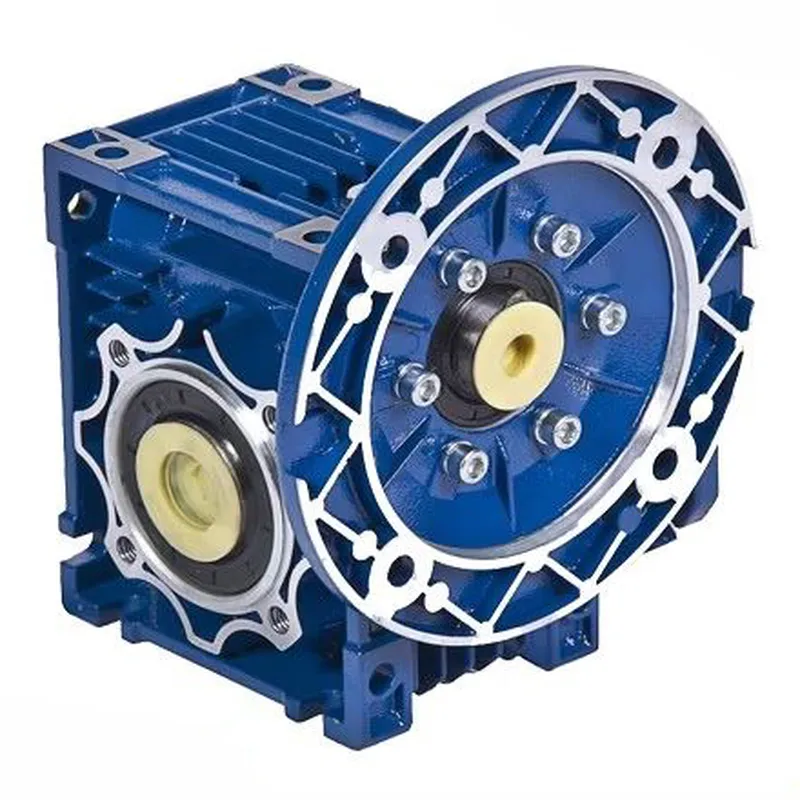
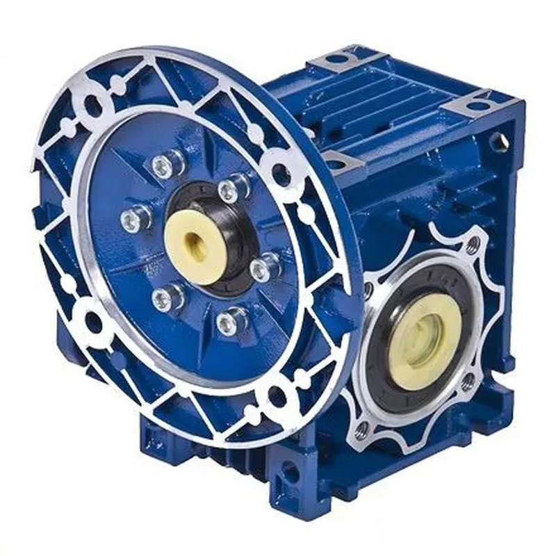
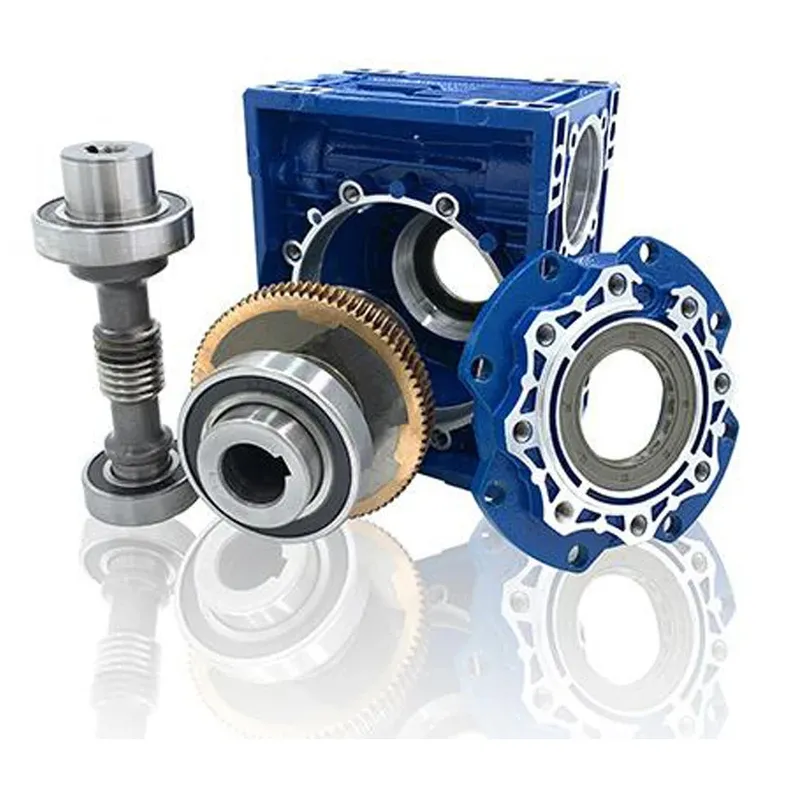
The CMN-NMRV040 worm gear reducer, also known as a worm gearbox, is a compact, high-performance mechanical device designed to reduce rotational speed and increase torque in various applications. It features a worm gear system, consisting of a worm (a screw-like component) and a worm wheel (a toothed wheel), which work together to achieve a high gear reduction ratio. They are widely used in conveyor systems, material handling equipment, packaging machines, and other industrial applications due to their smooth operation, low noise, and efficiency.
The CMN-NMRV040 worm gear reducer, also known as a worm gearbox, is a compact, high-performance mechanical device designed to reduce rotational speed and increase torque in various applications. It features a worm gear system, consisting of a worm (a screw-like component) and a worm wheel (a toothed wheel), which work together to achieve a high gear reduction ratio. The "040" in the name refers to the frame size of the gearbox, indicating a specific dimension standard.
These worm gear reducers are made from lightweight, corrosion-resistant aluminum alloy housing, making them durable and suitable for demanding environments. They are widely used in conveyor systems, material handling equipment, packaging machines, and other industrial applications due to their smooth operation, low noise, and efficiency. Additionally, CMN-NMRV040 units are compact, easy to install, and highly adaptable, often featuring modular mounting options for flexibility in various setups.
CMN-NMRV040 Worm Gearbox Specifications
| Typ | CMN-NMRV040 Worm Gearbox/ Worm Gear Speed Reducer |
| Model | CMN-NMRV040 |
| Współczynnik redukcji | 5,7.5,10,15,20,25,30,40,50,60,80,100 |
| Kołnierz | FA / FL lub zgodnie z Twoimi wymaganiami |
| Dopasowany silnik | 0,06 kW~15 kW |
| Tworzywo | Odlew ciśnieniowy ze stopu aluminium |
| Kolor | Niebieski /Srebrnoszary /Dostosowany |
| Kołnierz standardowy | PAM / IEC |
| Akcesoria | Wał, kołnierz, ramię momentu obrotowego itp. |
| Smar | Olej syntetyczny lub olej do przekładni ślimakowej |
| Stosowanie | Maszyny do przemysłu spożywczego, ceramicznego, chemicznego, pakującego, farbiarskiego, drzewnego, szklarskiego itp. |
| Notatka: 1) Proszę wybrać z powyższych specyfikacji. 2) Jeśli powyższe opcje nie spełnią Twoich oczekiwań, prześlij nam swoje wymagania (współczynnik, kołnierz, mocowanie, zastosowanie lub zdjęcie starego rozwiązania), a my zaproponujemy odpowiedni typ. | |
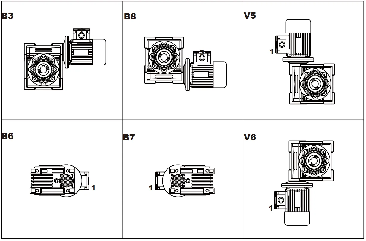
Pozycja montażu
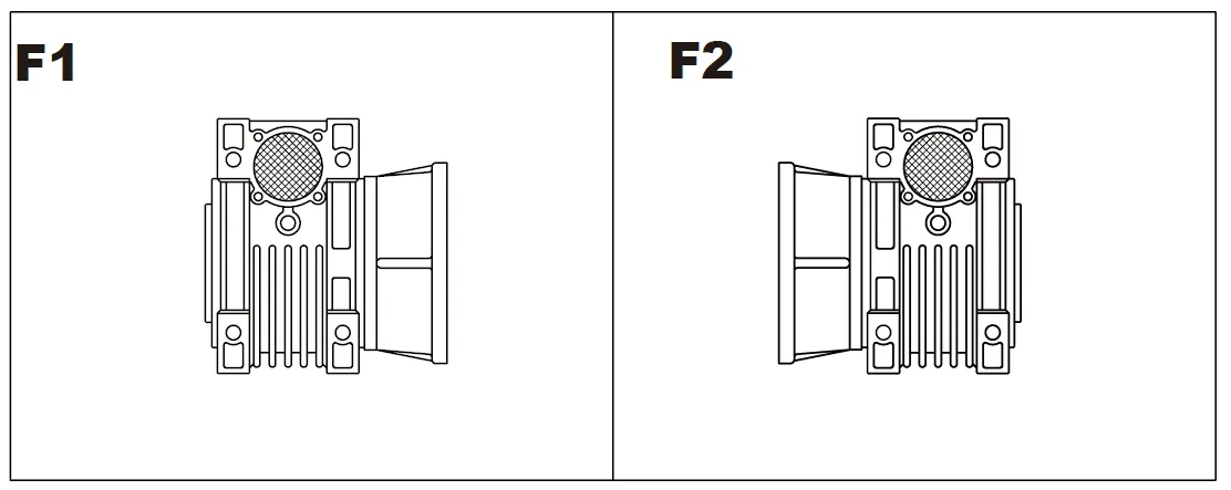
Kołnierz F-FL
Pozycja skrzynki zaciskowej
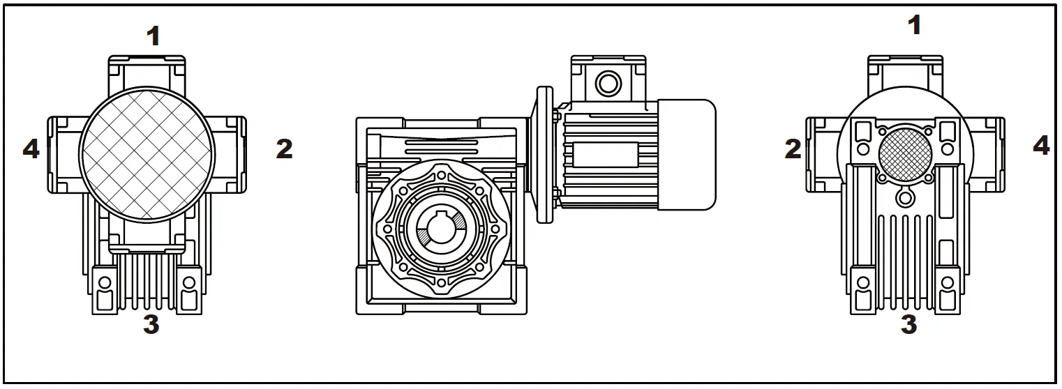
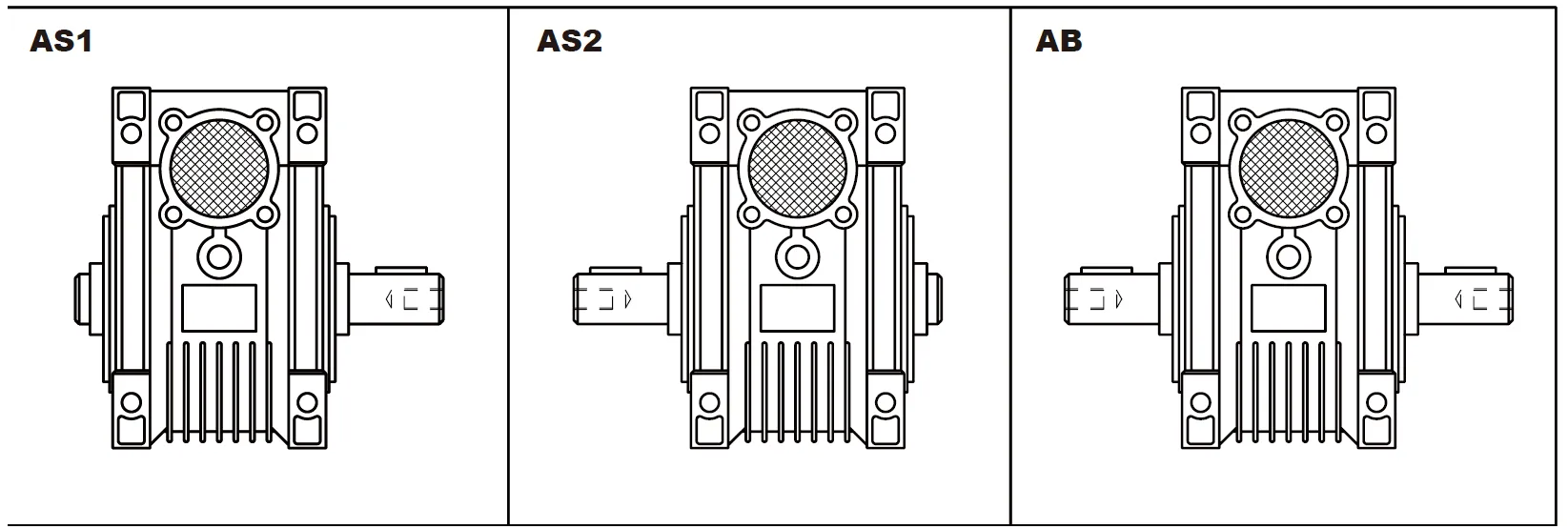
Pozycja wału wyjściowego
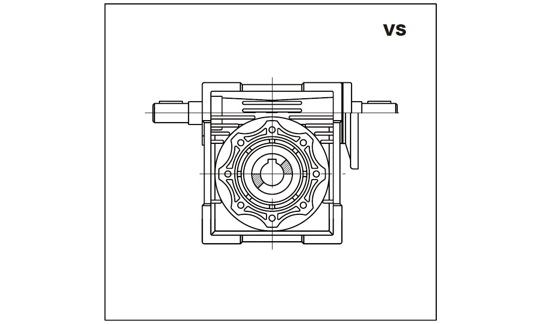
Podwójny wał ślimakowy
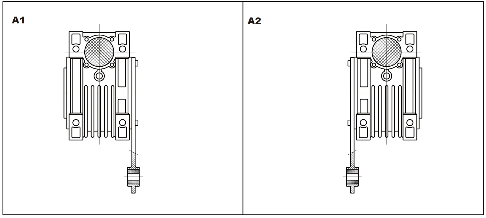
Pozycja ramienia momentu obrotowego
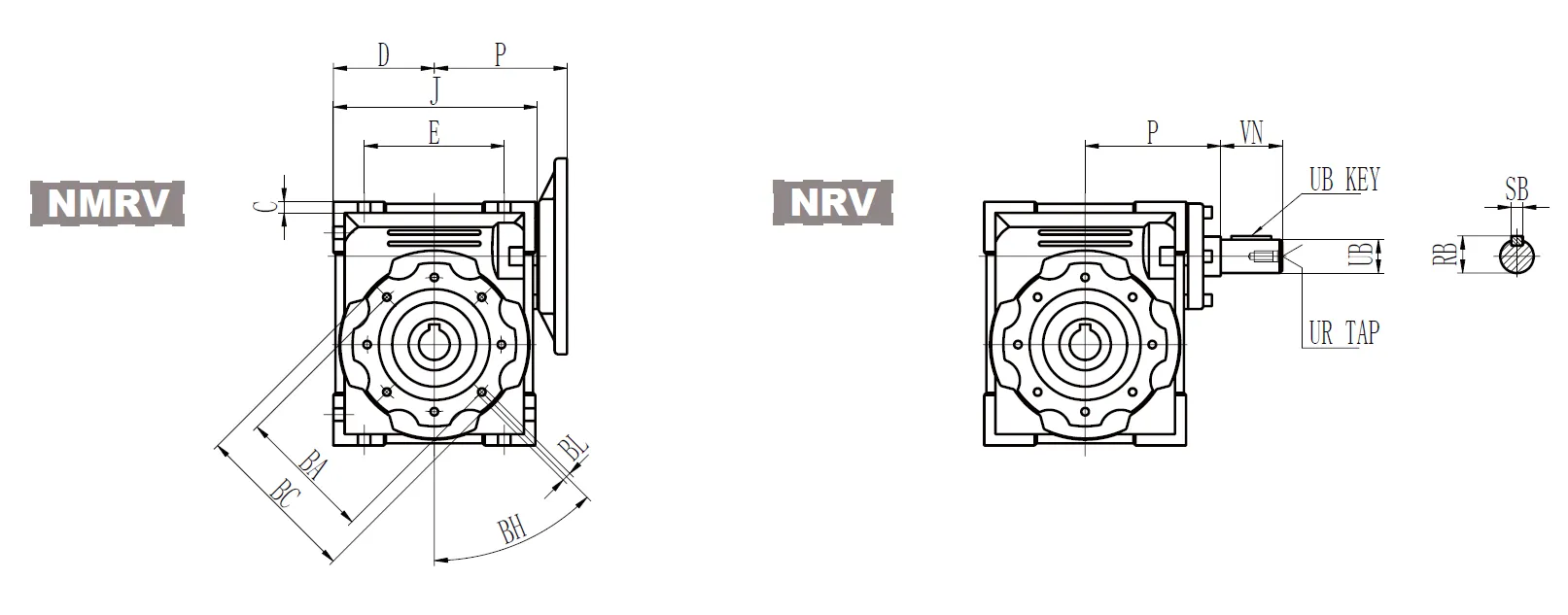
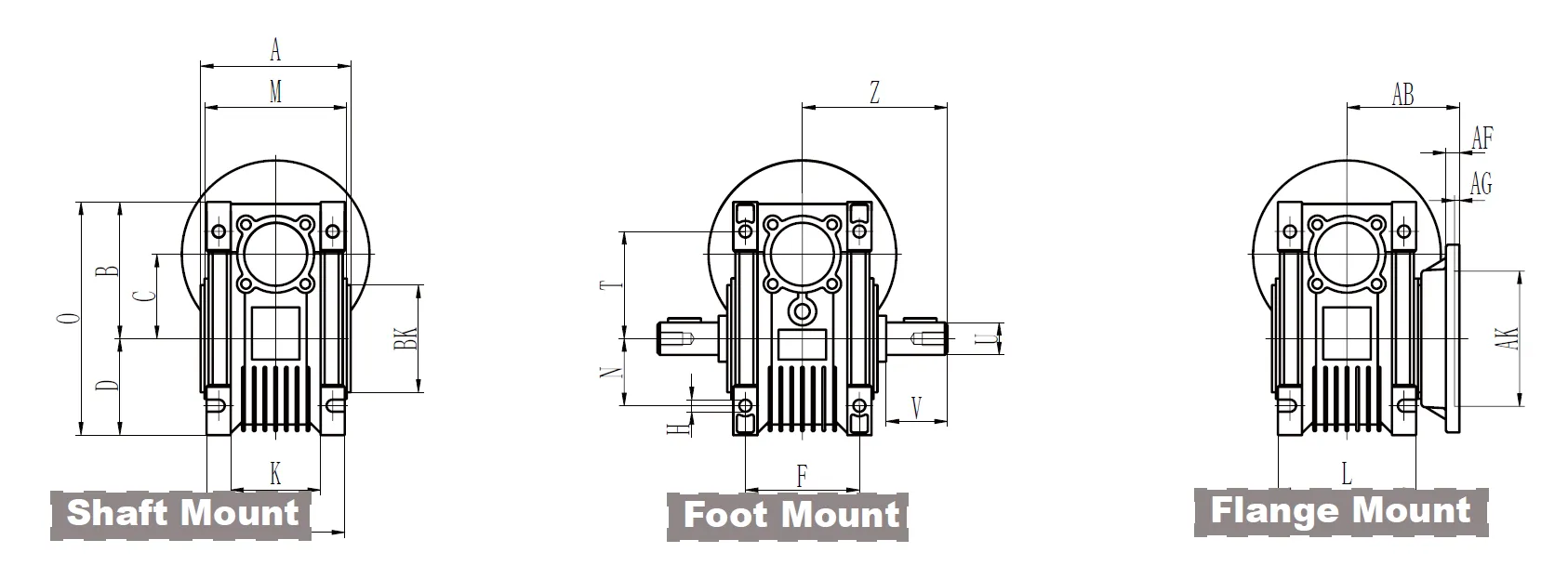
CMN-NMRV040 Worm Gear Reducer Dimensions
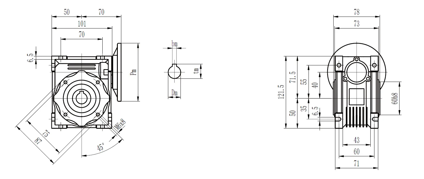
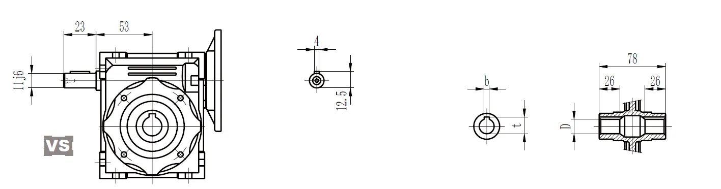
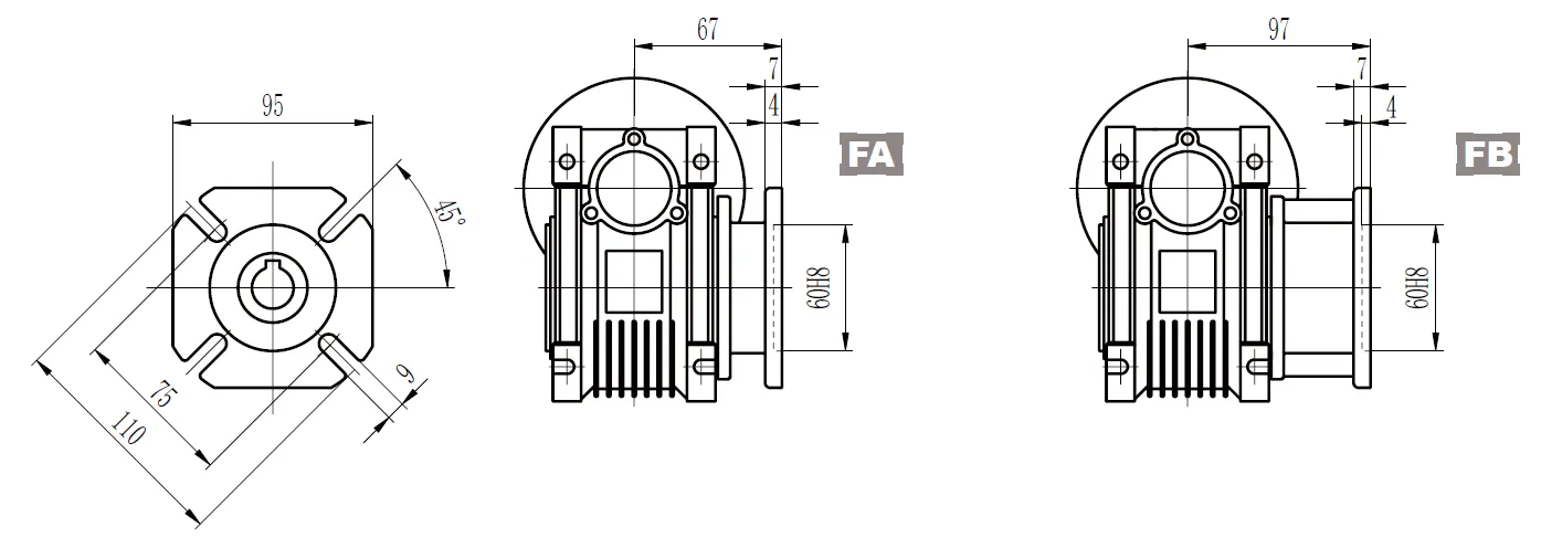
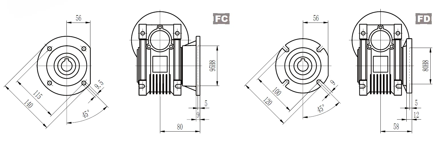
Wymiary przekładni ślimakowej CMN-NMRV
Seria calowa CMN-NMRV
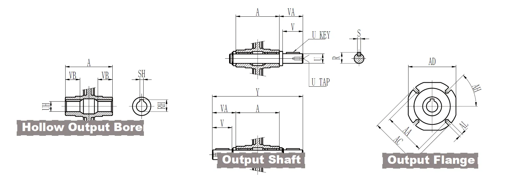
| Pusty otwór wyjściowy | 030 | 040 | 050 | 063 | 075 | 090 | 110 | 130 | |
| RH | 0.71 | 0.84 | 1.12 | 1.24 | 1.37 | 1.52 | 1.8 | 1.93 | |
| CII | 0.188 | 0.188 | 0.25 | 0.25 | 0.25 | 0.313 | 0.375 | 0.375 | |
| UH | 0.625+0.001 0 | 0.75+0.001 0 | 1+0.001 0 | 1.125+0.001 0 | 1.25+0.001 0 | 1.375+0.001 0 | 1.625+0.001 0 | 1.750 | |
| VB | 0.83 | 1.14 | 1.28 | 1.42 | 1.56 | 1.77 | 1.97 | 2.24 | |
| Wał wyjściowy | 030 | 040 | 050 | 063 | 075 | 090 | 110 | 130 | |
| R | 0.7 | 0.83 | 1.11 | 1.23 | 1.36 | 1.51 | 1.79 | 1.92 | |
| S | 0.188 | 0.188 | 0.25 | 0.25 | 0.25 | 0.313 | 0.375 | 0.375 | |
| U | 0.6250 -0.0005 | 0.750 -0.0005 | 10 -0.0005 | 0 -0.0005 | 1.250 -0.0005 | 1.3750 -0.0005 | 1.6250 -0.0005 | 1.750 -0.0005 | |
| KLUCZ U | 0,1875 x 1,125 | 0,1875 x 1,5 | 0,25x1,5 | 0,25 x 1,875 | 0,25x2,25 | 0,3125x2,5 | 0,375x2,75 | 0,375x2,75 | |
| UT | 1/4-20 | 1/4-20 | 3/8-16 | 3/8-16 | 1/2-13 | 1/2-13 | 5/8-11 | 5/8-11 | |
| V | 1.57 | 1.97 | 1.97 | 2.36 | 2.76 | 3.15 | 3.54 | 3.54 | |
| VA | 1.67 | 2.09 | 2.11 | 2.5 | 2.89 | 3.33 | 3.72 | 3.74 | |
| Y | 5.82 | 7.25 | 7.84 | 9.41 | 10.5 | 12.17 | 13.54 | 14.17 | |
| CMN-NMRV | 030 | 040 | 050 | 063 | 075 | 090 | 110 | 130 |
| A | 2.48 | 3.07 | 3.62 | 4.41 | 4.72 | 5.51 | 6.1 | 6.69 |
| B | 2.24 | 2.81 | 3.31 | 4.02 | 4.69 | 5.31 | 6.59 | 7.38 |
| BA | 2.56 | 2.95 | 3.35 | 3.74 | 4.53 | 5.12 | 6.5 | 8.46 |
| PRZED CHRYSTUSEM | 2.95 | 3.43 | 3.94 | 4.33 | 5.51 | 6.3 | 7.87 | 9.84 |
| BH | 90° | 45° | 45° | 45° | 45° | 45° | 45° | 45° |
| BK | 2.165 0 -0.0018 | 2.362 0 -0.0018 | 2.756 0 -0.0018 | 3.15 0 -0.0021 | 3.74 0 -0.0021 | 4.331 0 -0.0021 | 5.118 0 -0.0025 | 7.087 0 -0.0025 |
| BL | M6x11 | M6x10 | M8x10 | M8x14 | M8x14 | M10x18 | M10x18 | M12x21 |
| C | 1.18 | 1.57 | 1.97 | 2.48 | 2.95 | 3.54 | 4.33 | 5.12 |
| D | 1.57 | 1.97 | 2.36 | 2.83 | 3.39 | 4.06 | 5.02 | 5.81 |
| mi | 2.13 | 2.76 | 3.15 | 3.94 | 4.72 | 5.51 | 6.69 | 7.87 |
| F | 1.73 | 2.36 | 2.76 | 3.35 | 3.54 | 3.94 | 4.53 | 4.72 |
| G | 0.22 | 0.26 | 0.28 | 0.31 | 0.39 | 0.43 | 0.57 | 0.61 |
| H | 0.26 | 0.26 | 0.33 | 0.33 | 0.45 | 0.51 | 0.55 | 0.63 |
| J | 3.15 | 3.98 | 4.76 | 5.75 | 6.85 | 8.19 | 9.94 | 11.52 |
| K | 1.26 | 1.69 | 1.93 | 2.64 | 2.83 | 2.91 | - | - |
| L | 2.2 | 2.8 | 3.35 | 4.06 | 4.41 | 5.12 | 5.67 | 6.1 |
| M | 2.28 | 2.87 | 3.43 | 4.17 | 4.49 | 5.28 | 5.83 | 6.38 |
| N | 1.06 | 1.38 | 1.57 | 1.97 | 2.36 | 2.76 | 3.35 | 3.94 |
| O | 3.82 | 4.78 | 5.67 | 6.85 | 8.07 | 9.37 | 11.61 | 13.19 |
| P | 2.64 | 3.15 | 3.54 | 4.13 | 4.96 | 5.63 | 6.81 | 7.6 |
| Q | 0.83 | 2.36 | 2.91 | 3.54 | 4.13 | 4.92 | 5.59 | 6.38 |
| T | 1.73 | 2.17 | 2.52 | 3.15 | 3.66 | 4.02 | 4.92 | 5.51 |
| Z | 2.91 | 3.63 | 3.92 | 4.71 | 5.25 | 6.09 | 6.77 | 7.09 |
| Kołnierz wyjściowy | AA | AB | AC | OGŁOSZENIE | AF | AG | AH | AK | glin | ||
| 030 | FA | 2.68 | 2.15 | 3.15 | 2.76 | 0.24 | 0.16 | 45° | 1.969 | +0.0015 0 | 0.26 |
| 040 | FA | 2.95 | 2.64 | 4.33 | 3.74 | 0.28 | 0.16 | 45° | 2.362 | +0.0018 | 0.35 |
| 0 | |||||||||||
| pełne wyżywienie | 2.95 | 3.82 | 4.33 | 3.74 | 0.28 | 0.16 | 45° | 2.362 | +0.0018 0 | 0.35 | |
| FC | 4.53 | 3.15 | 5.51 | - | 0.35 | 0.2 | 45° | 3.74 | +0.0021 0 | 0.37 | |
| FD | 3.94 | 2.28 | 4.72 | - | 0.47 | 0.2 | 45° | 3.15 | +0.0018 | 0.35 | |
| 0 | |||||||||||
| 050 | FA | 3.35 | 3.54 | 4.92 | 4.33 | 0.35 | 0.2 | 45° | 2.756 | +0.0018 | 0.43 |
| 0 | |||||||||||
| pełne wyżywienie | 3.35 | 4.72 | 4.92 | 4.33 | 0.35 | 0.2 | 45° | 2.756 | +0.0018 0 | 0.43 | |
| FC | 5.12 | 3.5 | 6.3 | - | 0.39 | 0.2 | 45° | 4.331 | +0.0021 0 | 0.37 | |
| FD | 4.53 | 2.83 | 5.51 | - | 0.57 | 0.2 | 45° | 3.543 | +0.0021 | 0.43 | |
| 0 | |||||||||||
| 063 | FA | 4.13 | 3.23 | 7.09 | 5.59 | 0.39 | 0.24 | 45° | 4.528 | +0.0021 | 0.43 |
| 0 | |||||||||||
| pełne wyżywienie | 5.91 | 4.41 | 7.09 | 5.59 | 0.39 | 0.24 | 45° | 4.528 | +0.0021 | 0.43 | |
| 0 | |||||||||||
| FC | 6.5 | 3.86 | 7.87 | - | 0.39 | 0.2 | 45° | 5.118 | +0.0025 0 | 0.43 | |
| FD | 6.5 | 4.21 | 7.87 | - | 0.39 | 0.2 | 45° | 5.118 | +0.0025 | 0.43 | |
| 0 | |||||||||||
| FE | 5.12 | 3.17 | 6.3 | - | 0.65 | 0.2 | 45° | 4.331 | +0.0021 | 0.43 | |
| 0 | |||||||||||
| 075 | FA | 6.5 | 4.37 | 7.87 | 6.69 | 0.51 | 0.24 | 45° | 5.118 | +0.0025 | 0.55 |
| 0 | |||||||||||
| pełne wyżywienie | 5.12 | 3.54 | 6.3 | - | 0.51 | 0.24 | 45° | 4.331 | +0.0021 | 0.55 | |
| 0 | |||||||||||
| 090 | FA | 6.89 | 4.37 | 8.27 | 8.27 | 0.51 | 0.24 | 45° | 5.984 | +0.0025 | 0.55 |
| 0 | |||||||||||
| pełne wyżywienie | 8.46 | 4.8 | 9.84 | - | 0.71 | 0.24 | 45° | 7.087 | +0.0025 0 | 0.55 | |
| FC | 6.5 | 4.33 | 7.87 | - | 0.67 | 0.24 | 45° | 5.118 | +0.0025 0 | 0.43 | |
| FD | 6.89 | 5.94 | 8.27 | - | 0.51 | 0.24 | 45° | 5.984 | +0.0025 | 0.55 | |
| 0 | |||||||||||
| 110 | FA | 9.06 | 5.16 | 11.02 | 10.24 | 0.59 | 0.24 | 45° | 6.693 | +0.0025 | 0.55 |
| 0 | |||||||||||
| pełne wyżywienie | 9.06 | 7.09 | 11.02 | 10.24 | 0.59 | 0.24 | 45° | 6.693 | +0.0025 | 0.55 | |
| 0 | |||||||||||
| 130 | FA | 10.04 | 5.51 | 12.6 | 11.42 | 0.59 | 0.24 | 22,5° | 7.087 | +0.0025 0 | 0.63 |
| Wał wejściowy | 030 | 040 | 050 | 063 | 075 | 090 | 110 | 130 | |
| SB | 0.094 | 0.125 | 0.188 | 0.188 | 0.188 | 0.188 | 0.25 | 0.25 | |
| RB | 0.42 | 0.55 | 0.7 | 0.83 | 0.96 | 0.96 | 1.24 | 1.36 | |
| UB | 0.3750 -0.0005 | 0.50 -0.0005 | 0.6250 -0.0005 | 0.750 -0.0005 | 0.8750 -0.0005 | 0.8750 -0.0005 | 1.1250 -0.0005 | 1.250 -0.0005 | |
| KLUCZ UB | 0,094x0,875 | 0,125x0,875 | 0,1875 x 1,125 | 0,1875 x 1,5 | 0,1875 x 1,875 | 0,1875 x 1,875 | 0,25x2,25 | 0,25x2,5 | |
| UR | - | 1/4-20 | 1/4-20 | 1/4-20 | 1/4-20 | 1/4-20 | 3/8-16 | 1/2-13 | |
| VN | 1.18 | 1.18 | 1.58 | 1.97 | 2.36 | 2.36 | 2.76 | 3.15 | |
Wymiary wału przedłużającego o dużej prędkości
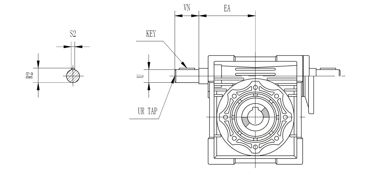
| CMN-NMRV | EA | U | VN | UR | S2 | R2 | KLAWISZ | |
| Długość | Kwadrat | |||||||
| 030 | 1.772 | 0.3750 -0.0005 | 1.18 | - | 0.093 | 0.42 | 0.875 | 0.094 |
| 040 | 2.087 | 0.50 -0.0005 | 1.18 | 1/4-20 | 0.13 | 0.55 | 0.875 | 0.125 |
| 050 | 2.52 | 0.6250 -0.0005 | 1.58 | 1/4-20 | 0.19 | 0.7 | 1.125 | 0.188 |
| 063 | 2.953 | 0.750 -0.0005 | 1.97 | 1/4-20 | 0.19 | 0.83 | 1.5 | 0.188 |
| 075 | 3.543 | 0.8750 -0.0005 | 2.36 | 1/4-20 | 0.19 | 0.96 | 1.875 | 0.188 |
| 090 | 4.252 | 0.8750 -0.0005 | 2.36 | 1/4-20 | 0.19 | 0.96 | 1.875 | 0.188 |
| 110 | 5.315 | 1.1250 -0.0005 | 2.76 | 3/8-16 | 0.25 | 1.24 | 2.25 | 0.25 |
| 130 | 6.102 | 1.250 -0.0005 | 3.15 | 1/2-13 | 0.25 | 1.36 | 2.5 | 0.25 |
Wymiary ramienia reakcyjnego
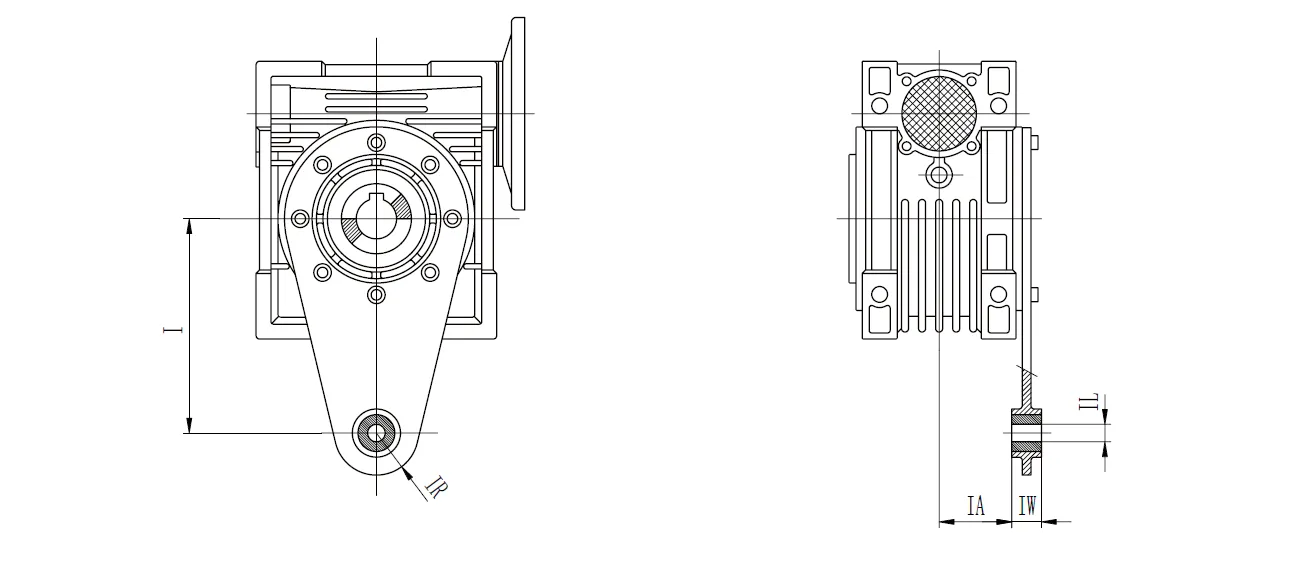
| I | IA | IL | IR | IW | |
| 025 | 2.76 | 0.69 | 0.31 | 0.59 | 0.55 |
| 030 | 3.35 | 0.94 | 0.31 | 0.59 | 0.55 |
| 040 | 3.94 | 1.24 | 0.39 | 0.71 | 0.55 |
| 050 | 3.94 | 1.52 | 0.39 | 0.71 | 0.55 |
| 063 | 5.91 | 1.93 | 0.39 | 0.71 | 0.55 |
| 075 | 7.87 | 1.87 | 0.79 | 1.18 | 0.98 |
| 090 | 7.87 | 2.26 | 0.79 | 1.18 | 0.98 |
| 110 | 9.84 | 2.44 | 0.98 | 1.38 | 1.18 |
| 130 | 9.84 | 2.72 | 0.98 | 1.38 | 1.18 |
Wymiary osłony ochronnej
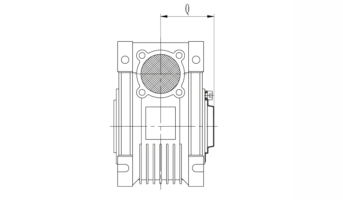
| CMN-NMRV | Q |
| 030 | 1.65 |
| 040 | 1.97 |
| 050 | 2.28 |
| 063 | 2.72 |
| 075 | 2.91 |
| 090 | 3.39 |
| 110 | 3.7 |
| 130 | 4.02 |
Dostępność kołnierza NEMA
| CMN-NMRV | NEMA Kołnierz | Otwór wejściowy Średnica | Dostępne współczynniki | |||||||||||
| 5 | 7.5 | 10 | 15 | 20 | 25 | 30 | 40 | 50 | 60 | 80 | 100 | |||
| 030 | 48C | 0.5 | ● | ● | ● | ● | ● | ● | ● | ● | ● | ● | ● | |
| 040 | 56 stopni Celsjusza | 0.625 | ● | ● | ● | ● | ● | ● | ● | ● | ● | ● | ● | ● |
| 050 | 56 stopni Celsjusza | 0.625 | ● | ● | ● | ● | ● | ● | ● | ● | ● | ● | ● | ● |
| 063 | 56 stopni Celsjusza | 0.625 | ● | ● | ● | ● | ● | ● | ● | ● | ||||
| 140TC | 0.875 | ● | ● | ● | ● | ● | ● | ● | ||||||
| 075 | 56 stopni Celsjusza | 0.625 | ● | ● | ● | ● | ||||||||
| 140TC | 0.875 | ● | ● | ● | ● | ● | ● | |||||||
| 180TC | 1.125 | ● | ● | ● | ||||||||||
| 090 | 56 stopni Celsjusza | 0.625 | ● | ● | ||||||||||
| 140TC | 0.875 | ● | ● | ● | ● | ● | ||||||||
| 180TC | 1.125 | ● | ● | ● | ● | ● | ● | ● | ||||||
| 110 | 140TC | 0.875 | ● | ● | ● | ● | ||||||||
| 180TC | 1.125 | ● | ● | ● | ● | ● | ● | |||||||
| 210TC | 1.375 | ● | ● | ● | ● | |||||||||
| 130 | 140TC | 0.875 | ● | ● | ||||||||||
| 180TC | 1.125 | ● | ● | ● | ● | ● | ||||||||
| 210TC | 1.375 | ● | ● | ● | ● | ● | ● | ● | ||||||
CMN-NMRV040 Worm Drive Gearbox Features
- Kompaktowa i trwała konstrukcja
The CMN-NMRV040 worm drive gearbox features a high-strength aluminum alloy housing, ensuring corrosion resistance and efficient heat dissipation. Its compact design allows for easy integration into space-constrained applications, providing robust performance in industries like food processing and textiles. - Wysoki moment obrotowy
With reduction ratios ranging from 5:1 to 100:1, the CMN-NMRV040 worm reducer gearbox delivers substantial torque for low to medium-speed applications. The worm and worm wheel configuration ensures efficient power transmission, making it ideal for heavy-duty tasks requiring precise control and high force. - Wszechstronne opcje montażu
The worm gear gearbox supports multiple mounting configurations, including flange inputs like 71B5 and 63B14. This flexibility enables seamless compatibility with various motor types, such as NEMA 34 or smaller stepper and servo motors, enhancing adaptability across diverse industrial setups. - Płynna i cicha praca
Precision-engineered worm and worm wheel components, typically made from bronze or nodular cast iron, ensure smooth and quiet performance. The CMN-NMRV040 worm gear speed reducer minimizes vibration and noise, making it suitable for noise-sensitive environments like medical or packaging equipment. - Możliwość samoblokowania
The worm gear design provides inherent self-locking, preventing back-driving under load. This feature enhances safety in applications like hoisting or lifting, ensuring the system remains stable even when power is off, reducing the need for additional braking mechanisms. - Low Maintenance and Longevity
Filled with synthetic oil, the CMN-NMRV040 worm gear reduction gearbox requires minimal maintenance while offering excellent lubrication for an extended lifespan. Its robust construction and high-quality materials ensure reliable operation under demanding conditions, reducing downtime and maintenance costs in industrial settings.
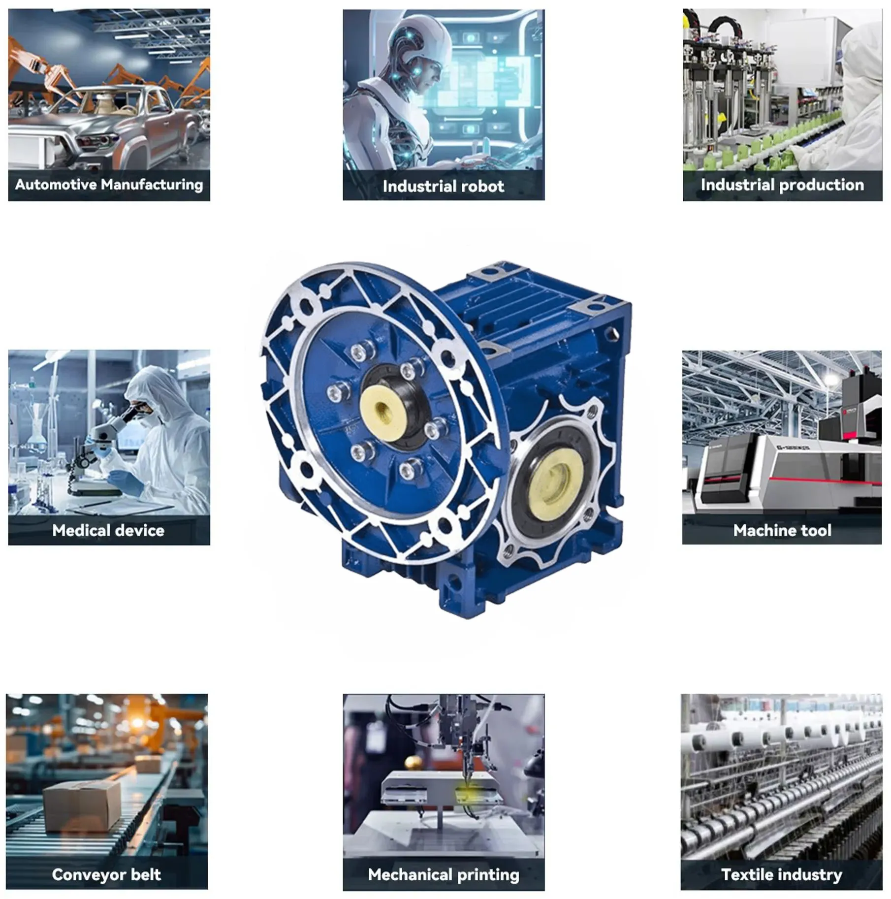
CMN-NMRV040 Worm Reducer Gearbox Applications
- Przemysł przetwórstwa spożywczego
The CMN-NMRV040 worm reducer gearbox is widely used in food processing for conveyors and mixers. Its corrosion-resistant aluminum housing and smooth operation ensure hygiene and reliability, meeting strict industry standards while handling precise speed control for consistent production processes. - Produkcja tekstyliów
In textile machinery, the right angle worm gearbox drives spinning and weaving equipment. Its high torque and self-locking feature provide stable operation under varying loads, ensuring precision in fabric production, while its compact design fits seamlessly into space-constrained textile manufacturing setups. - Maszyny pakujące
The CMN-NMRV040 worm and wheel gearbox is ideal for packaging systems, powering rollers, and labeling machines. Its quiet operation and versatile mounting options enable integration into automated lines, delivering consistent torque for high-speed packaging tasks while maintaining reliability in demanding environments. - Produkcja ceramiki
In ceramics manufacturing, the worm gear drive gearbox supports equipment like clay mixers and kilns. Its robust construction withstands harsh conditions, while the high reduction ratios ensure precise speed control, enhancing efficiency in shaping and processing ceramic materials with minimal maintenance. - Systemy transportu materiałów
The CMN-NMRV040 worm gearbox motor is employed in material handling for conveyors and hoists. Its self-locking capability ensures safety during load lifting, while the compact design and high torque output facilitate efficient movement of goods in warehouses and logistics operations. - Automatyka i robotyka
In automation, the worm reduction gearbox drives robotic arms and automated guided vehicles. Its compatibility with stepper and servo motors, combined with low noise and precise torque delivery, supports accurate positioning and smooth operation in advanced robotic systems across various industries.
CMN-NMRV040 Worm Gear Reducer Troubleshooting
- Nadmierny hałas podczas pracy
Excessive noise can result from improper lubrication, misalignment of the worm and wheel, or worn-out bearings. Regularly inspect and replace worn components and ensure the gearbox is properly lubricated with the correct grade of oil to maintain smooth operation. - Overheating of the Gearbox
Overheating occurs due to excessive load, improper lubrication, or insufficient ventilation. Check the load to ensure it does not exceed the gearbox's capacity. Confirm that the lubricant is at the appropriate level and that the unit has adequate airflow for cooling. - Oil Leakage from the Housing
Oil leaks are often caused by damaged seals, loose bolts, or overfilling of lubricant. Inspect the seals for any wear or damage, tighten all bolts to recommended torque settings, and ensure the correct amount of lubricant is used to prevent overflow. - Reduced Torque Output
A drop in torque output can be due to worn gear teeth, excessive backlash, or improper engagement of the worm and wheel. Inspect the gear teeth for wear, adjust the backlash if necessary, and ensure proper alignment of all internal components. - Gearbox Not Rotating Smoothly
If the gearbox rotates unevenly or gets stuck, it could be due to debris inside the housing, damaged gears, or insufficient lubrication. Disassemble the unit for cleaning, inspect for damaged components, and reassemble with proper lubrication to restore smooth operation. - Unusual Vibrations During Use
Unusual vibrations may result from unbalanced loads, misalignment, or damaged internal components. Check the load balance to ensure even distribution, verify alignment between the gearbox and connected machinery, and replace any damaged gears or bearings to eliminate vibrations.
Informacje dodatkowe
| Edytowane przez | Yjx |
|---|