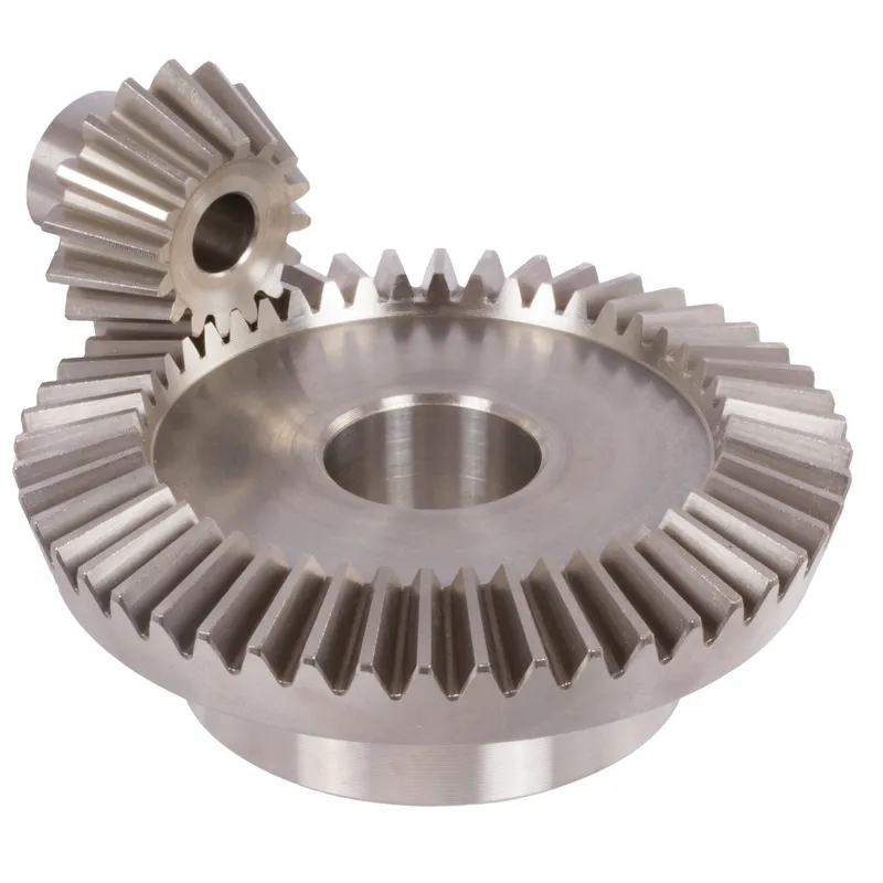
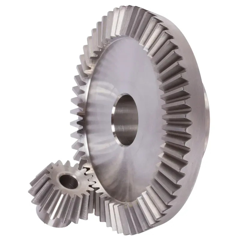
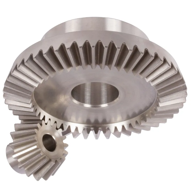
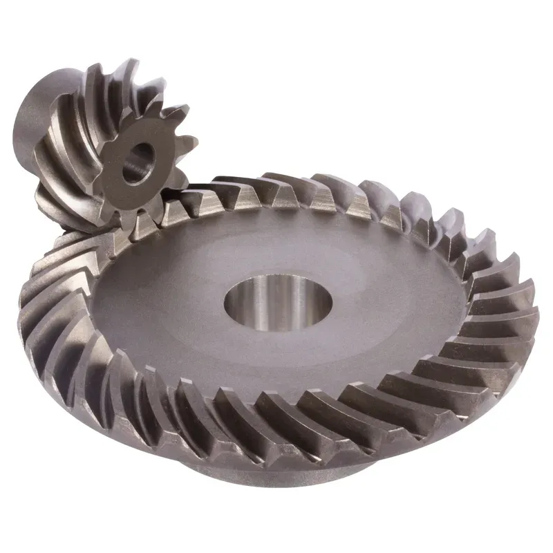
Przekładnie stożkowe ze stali nierdzewnej o stosunku 4:1 i zębach prostych
Przekładnie stożkowe ze stali nierdzewnej o przełożeniu 4:1 i zębach prostych to mechaniczne rozwiązanie zaprojektowane do efektywnego przenoszenia mocy między dwoma przecinającymi się wałami, zazwyczaj pod kątem prostym (90°). Te przekładnie stożkowe wykonane są z wytrzymałej stali nierdzewnej, oferując doskonałą odporność na korozję, zużycie i wysokie temperatury, dzięki czemu nadają się do wymagających zastosowań przemysłowych.
Przekładnie stożkowe ze stali nierdzewnej o przełożeniu 4:1 i zębach prostych to mechaniczne rozwiązanie zaprojektowane do efektywnego przenoszenia mocy między dwoma przecinającymi się wałami, zazwyczaj pod kątem prostym (90°). Te przekładnie stożkowe wykonane są z wytrzymałej stali nierdzewnej, oferując doskonałą odporność na korozję, zużycie i wysokie temperatury, dzięki czemu nadają się do wymagających zastosowań przemysłowych.
Przełożenie 4:1 oznacza, że mniejsze koło zębate (zębnik) wykonuje cztery obroty na każdy obrót większego koła zębatego. Pozwala to na znaczne zmniejszenie prędkości przy jednoczesnym zwiększeniu momentu obrotowego. Konstrukcja z zębami prostymi odnosi się do liniowych, promieniowo ułożonych zębów koła zębatego, które są prostsze w produkcji i regulacji w porównaniu z kołami stożkowymi o zębach spiralnych. Chociaż są nieco głośniejsze ze względu na nagłe zazębienie, idealnie nadają się do zastosowań o niskiej i średniej prędkości, gdzie precyzja i trwałość są kluczowe.
Przekładnia stożkowa ze stali nierdzewnej o przełożeniu 4:1
| 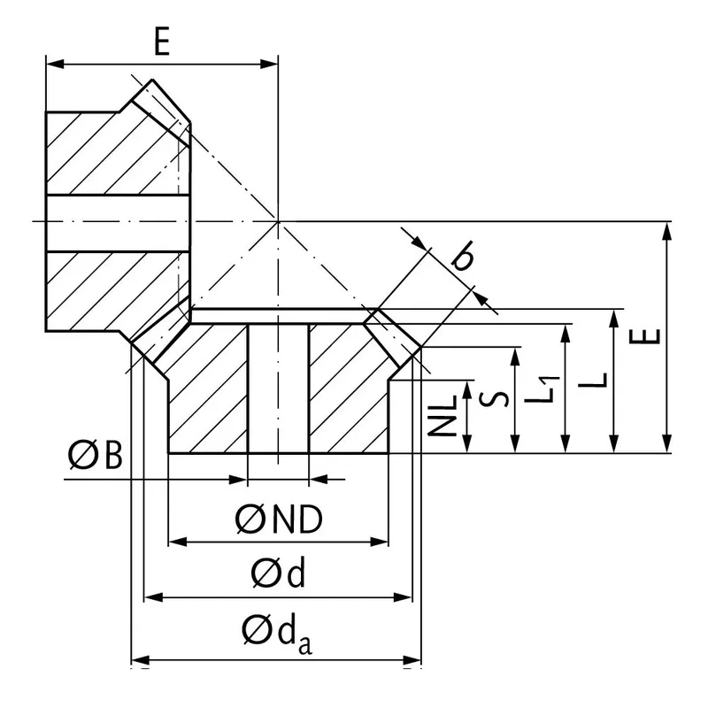 |
| Moduł | Numer zębów | DA | D | ND | Holandia | L1 | L | S | B | BH7 | mi | Moment obrotowy* | Waga |
| mm | mm | mm | mm | mm | mm | mm | mm | mm | mm | Ncm | G | ||
| 1 | 15 | 17,8 | 15 | 13 | 7,7 | 17,3 | 17,3 | 8,4 | 9,3 | 5 | 38 | 0,14 | 15 |
| 1 | 60 | 60,3 | 60 | 30 | 10,0 | 15 | 17,1 | 15,1 | 9,3 | 8 | 22 | 0,56 | 160 |
| 1,5 | 15 | 26,7 | 22,5 | 18 | 14,45 | 28 | 28,9 | 15,5 | 13,9 | 8 | 60 | 0,48 | 42 |
| 1,5 | 60 | 90,4 | 90 | 50 | 12,0 | 25 | 27,6 | 24,6 | 13,9 | 15 | 35 | 1,92 | 745 |
| 2 | 15 | 34,0 | 30 | 20 | 13,5 | 29 | 29,9 | 15,5 | 15 | 10 | 75 | 1,34 | 80 |
| 2 | 60 | 120,9 | 120 | 60 | 20,0 | 35 | 40,1 | 37,0 | 15 | 25 | 50 | 5,36 | 1600 |
| 2,5 | 15 | 42,5 | 37,5 | 30 | 16,1 | 35 | 36,8 | 17,6 | 20 | 10 | 92 | 2,5 | 190 |
| 2,5 | 60 | 151,2 | 150 | 80 | 18,0 | 33 | 37,8 | 33,8 | 20 | 25 | 50 | 10,0 | 2600 |
| 3 | 15 | 51,0 | 45 | 30 | 13,15 | 38 | 39,7 | 15,7 | 25 | 10 | 105 | 4,4 | 270 |
| 3 | 60 | 181,5 | 180 | 80 | 18,0 | 35 | 40,6 | 35,5 | 25 | 30 | 55 | 17,6 | 3800 |
| 4 | 15 | 68,0 | 60 | 40 | 12,5 | 43 | 44,8 | 16,0 | 30 | 20 | 135 | 8,9 | 520 |
| 4 | 60 | 242,0 | 240 | 90 | 20,0 | 41 | 50,1 | 44,0 | 30 | 30 | 70 | 35,6 | 8300 |
Zalety przekładni stożkowych ze stali nierdzewnej
Wysoka nośność momentu obrotowego
Jedną z kluczowych zalet przekładni stożkowych ze stali nierdzewnej jest ich zdolność do przenoszenia obciążeń o wysokim momencie obrotowym. Geometria i konstrukcja przekładni stożkowych umożliwiają efektywne przenoszenie mocy i momentu obrotowego między zazębiającymi się wałami.
Kompaktowa konstrukcja
Przekładnie stożkowe oferują kompaktowe rozwiązanie do przenoszenia mocy między wałami nierównoległymi. Dzięki zastosowaniu geometrii stożkowej, przekładnie stożkowe mogą skutecznie zmieniać kierunek obrotów w ograniczonej przestrzeni.
Płynna i cicha praca
Prawidłowo zaprojektowane i wyprodukowane przekładnie stożkowe zapewniają płynną i cichą pracę. Postęp w geometrii zębów kół zębatych, taki jak zastosowanie przekładni stożkowych o zębach spiralnych i hipoidalnych, znacznie poprawił płynność pracy i zdolność redukcji hałasu przekładni stożkowych. Zakrzywiony profil zębów przekładni stożkowych o zębach spiralnych umożliwia stopniowe zazębianie i rozprzęganie, co przekłada się na cichszą pracę w porównaniu z przekładniami stożkowymi o zębach prostych.
Wszechstronność kątów wału
Przekładnie stożkowe oferują elastyczność pod względem kątów nachylenia wału, jakie mogą przyjąć. Chociaż najczęstszym kątem nachylenia wału w przekładniach stożkowych jest 90 stopni, można je zaprojektować do pracy z różnymi kątami nachylenia wału.
Wady przekładni stożkowych ze stali nierdzewnej
Wyższa złożoność produkcji
Jedną z głównych wad przekładni stożkowych ze stali nierdzewnej jest ich większa złożoność produkcyjna w porównaniu z innymi rodzajami przekładni, takimi jak koła zębate walcowe. Produkcja przekładni stożkowych wymaga specjalistycznych maszyn i precyzyjnych procesów produkcyjnych, aby uzyskać pożądaną geometrię zębów i wykończenie powierzchni. Ta złożoność może skutkować wyższymi kosztami produkcji i dłuższym czasem realizacji.
Wrażliwość na nieprawidłowe ustawienie
Przekładnie stożkowe są bardziej wrażliwe na niewspółosiowość niż inne rodzaje przekładni. Niewspółosiowość może prowadzić do nierównomiernego rozkładu obciążenia, zwiększonego obciążenia zębów przekładni i przedwczesnej awarii.
Ograniczona prędkość
Przekładnie stożkowe mają ograniczenia pod względem dopuszczalnej prędkości obrotowej. Przy wysokich prędkościach przekładnie stożkowe są podatne na generowanie nadmiernego hałasu i wibracji z powodu ślizgania się zębów. Może to prowadzić do obniżenia sprawności i zwiększonego zużycia. W rezultacie przekładnie stożkowe są zazwyczaj stosowane w zastosowaniach wymagających umiarkowanych lub niskich prędkości obrotowych.
Wyższy koszt
Złożoność i precyzja produkcji wymagana w przypadku przekładni stożkowych często przekładają się na wyższe koszty w porównaniu z prostszymi typami przekładni. Potrzeba specjalistycznych maszyn, wykwalifikowanej siły roboczej i rygorystycznych środków kontroli jakości przyczynia się do wzrostu kosztów przekładni stożkowych. Ponadto, wymagania dotyczące personalizacji i specyficznej konstrukcji przekładni stożkowych dla konkretnych zastosowań mogą dodatkowo zwiększyć ich koszt.
Do czego służą koła zębate stożkowe
Przenoszenie mocy w samochodach
Przekładnie stożkowe znajdują szerokie zastosowanie w przemyśle motoryzacyjnym, szczególnie w układach różnicowych. W mechanizmie różnicowym, proste przekładnie stożkowe służą do rozdzielania mocy z wału napędowego i przekazywania jej na koła, umożliwiając im jednocześnie obrót z różną prędkością. Umożliwia to płynne pokonywanie zakrętów i lepszą kontrolę trakcji. Przekładnie stożkowe są również wykorzystywane w innych zastosowaniach motoryzacyjnych, takich jak skrzynie rozdzielcze i układy kierownicze.
Maszyny przemysłowe
Przekładnie stożkowe są powszechnie stosowane w maszynach przemysłowych, gdzie moc musi być przenoszona między zazębiającymi się wałami. Występują w szerokiej gamie urządzeń, w tym w przekładniach, reduktorach prędkości i układach przeniesienia napędu. Zastosowania przemysłowe wykorzystujące przekładnie stożkowe obejmują maszyny górnicze, maszyny budowlane, prasy drukarskie i maszyny tekstylne.
Lotnictwo i kosmonautyka
Przemysł lotniczy i kosmiczny wykorzystuje przekładnie stożkowe ze stali nierdzewnej do przenoszenia mocy w różnych zastosowaniach. Przekładnie stożkowe są stosowane w silnikach lotniczych, układach napędowych wirników i przekładniach pomocniczych. Są one zaprojektowane do przenoszenia dużych obciążeń i zapewniają niezawodną pracę w wymagających warunkach pracy. Kompaktowa konstrukcja i możliwość przenoszenia mocy między wałami nierównoległymi sprawiają, że przekładnie stożkowe doskonale nadają się do zastosowań lotniczych, gdzie przestrzeń jest ograniczona.
Zastosowania morskie
Przekładnie stożkowe są stosowane w zastosowaniach morskich do przenoszenia mocy w układach napędowych, sterowych i maszynach pokładowych. Znajdują zastosowanie w przekładniach morskich, sterach strumieniowych i wciągarkach. Zdolność przekładni stożkowych do przenoszenia wysokich obciążeń momentem obrotowym i odporności na trudne warunki morskie sprawia, że nadają się one do tych zastosowań. Przekładnie stożkowe do zastosowań morskich są często produkowane z materiałów odpornych na korozję, co zapewnia ich trwałość i niezawodność.
 |  |
| Przekładnia stożkowa do mechanizmów różnicowych samochodowych | Przekładnia stożkowa do maszyn przemysłowych |
 |  |
| Przekładnia stożkowa do robotyki | Przekładnia stożkowa do przemysłu morskiego |
Pomiar przekładni stożkowej ze stali nierdzewnej
Krok 1: Zbierz niezbędne narzędzia i sprzęt
Aby dokładnie zmierzyć koła zębate stożkowe, potrzebne będą następujące narzędzia:
- Suwmiarka lub mikrometr do pomiaru grubości, głębokości i średnicy podziałowej zębów
- Kątomierz kątowy do pomiaru kątów podziałowych i kątów korzeniowych
- Suwmiarka zębata do pomiaru grubości zębów na określonej głębokości
- Płyta powierzchniowa i wskaźnik wysokości do sprawdzania bicia kół zębatych i odległości montażowej
Krok 2: Zmierz średnicę podziałową
Aby zmierzyć średnicę podziałową:
- Umieść przekładnię stożkową na płycie powierzchniowej, stroną tylną do dołu.
- Umieść wskaźnik wysokości prostopadle do płyty powierzchniowej i wyrównaj jego końcówkę pomiarową z linią podziałową na boku zęba koła zębatego.
- Wyzeruj wskaźnik wysokości w tym położeniu.
- Obróć koło zębate o 180 stopni i zmierz wysokość na odpowiedniej linii podziałowej na przeciwległym boku zęba.
- Średnicę podziałową oblicza się poprzez dodanie dwóch pomiarów wysokości.
Powtórz ten proces na kilku zębach dookoła koła zębatego, aby zapewnić spójność i sprawdzić, czy nie występują potencjalne problemy z biciem.
Krok 3: Zmierz grubość zęba
Aby zmierzyć grubość zęba:
- Użyj suwmiarki z zębami ustawionymi na linii podziałowej.
- Zmierz grubość zęba na linii podziałowej, uważając, aby nie uszkodzić profilu zęba.
- Powtórz pomiary na kilku zębach wokół koła zębatego, zwracając uwagę na wszelkie odchylenia.
Alternatywnie, do pomiaru grubości cięciwy u podstawy zęba można użyć standardowej suwmiarki lub mikrometru.
Krok 4: Zmierz ciśnienie i kąty korzeniowe
Aby zmierzyć te kąty:
- Umieść kątomierz na stożku podziałowym koła zębatego, wyrównując jego krawędź z powierzchnią boczną zęba.
- Odczytaj kąt nacisku bezpośrednio ze skali kątomierza w punkcie styczności z profilem zęba.
- Zmień położenie kątomierza tak, aby wyrównał się z linią korzenia zęba, aby zmierzyć kąt nachylenia korzenia.
Sprawdź, czy zmierzone kąty odpowiadają określonym parametrom konstrukcyjnym przekładni.
Krok 5: Sprawdź bicie kół zębatych
Bicie koła zębatego odnosi się do zmiany geometrii koła zębatego podczas obrotu wokół własnej osi. Aby sprawdzić bicie:
- Zamontuj przekładnię stożkową na trzpieniu lub wrzecionie podpartym blokami V na płycie powierzchniowej.
- Umieść czujnik zegarowy tak, aby jego sonda stykała się z tylną powierzchnią koła zębatego w pobliżu średnicy zewnętrznej.
- Powoli obracaj przekładnię, zwracając uwagę na całkowity odczyt wskaźnika (TIR) na tarczy.
- Porównaj zmierzony TIR z określoną tolerancją bicia.
Aby w pełni ocenić bicie koła zębatego, należy powtórzyć ten proces na przedniej powierzchni koła zębatego i na średnicy podziałowej.
Krok 6: Sprawdź odległość montażową
Odległość montażowa to położenie osiowe koła zębatego stożkowego względem koła pasowego. Aby sprawdzić odległość montażową:
- Umieść przekładnię stożkową na płycie powierzchniowej, przednią stroną do dołu.
- Za pomocą wysokościomierza zmierz odległość od płyty powierzchniowej do tylnej powierzchni koła zębatego przy określonym promieniu odległości montażowej.
- Porównaj ten pomiar z zaprojektowaną odległością mocowania przekładni.
Informacje dodatkowe
| Edytowane przez | Yjx |
|---|
Podobne produkty
-
Przekładnie stożkowe spiralne ze stali o stosunku zębów 4:1
-
Przekładnie stożkowe ze stali ukośnej o przełożeniu 1:1 i układzie zębów prostych
-
Przekładnie stożkowe ze stali nierdzewnej o przełożeniu 1:1 – 4:1, system zębów prostych
-
Przekładnie stożkowe spiralne ze stali o stosunku zębów 1:1 – 4:1
-
Przekładnie stożkowe mosiężne o przełożeniu 1,5:1, układ zębów prostych


