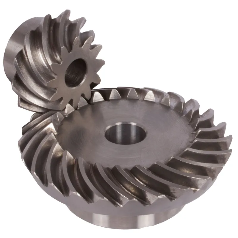
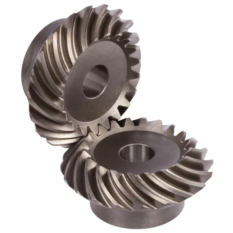
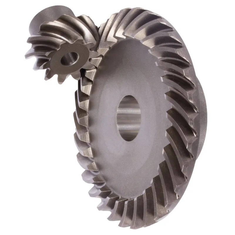
Przekładnie stożkowe spiralne ze stali o stosunku zębów 1:1 – 4:1
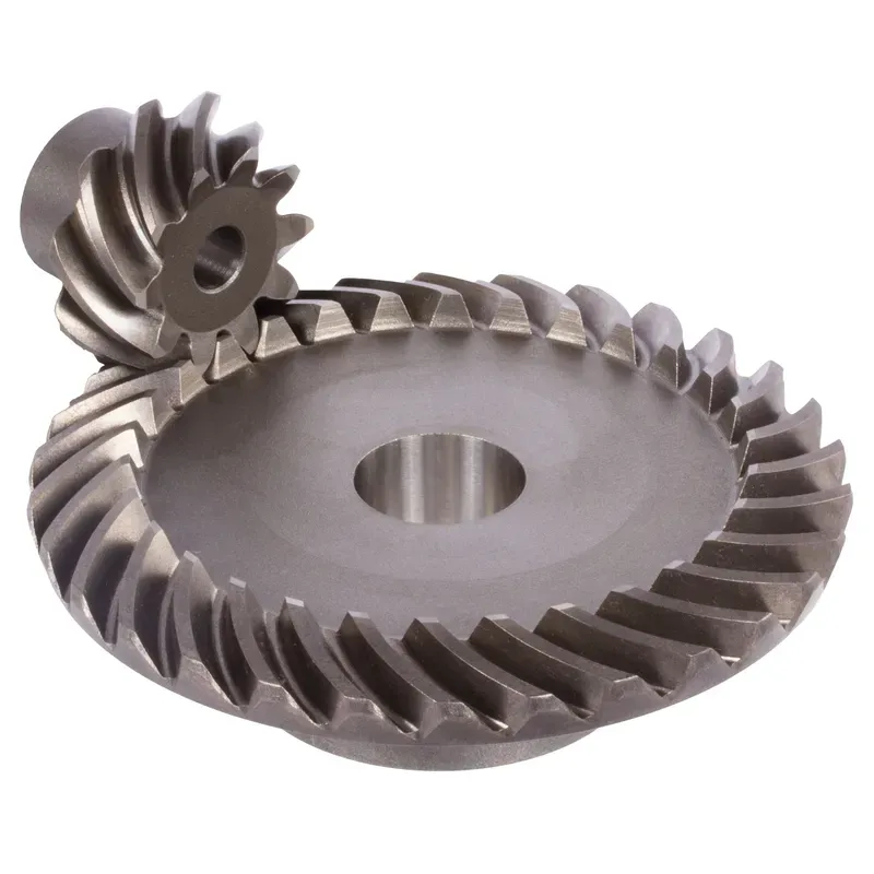
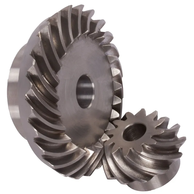
Steel spiral bevel gears with a ratio of 1.2:1 to 1.6:1 and a spiral tooth system are conical gears designed to transmit power between intersecting shafts, typically at a 90-degree angle. The spiral tooth design, with curved and angled teeth (often 35° spiral angle), ensures smoother and quieter operation compared to straight bevel gears due to gradual tooth engagement and higher contact ratios. These steel bevel gears are made from high-strength carbon or alloy steels like 42CrMo4 or 16MnCr5, suitable for moderate speed reductions in applications like automotive differentials or industrial machinery.
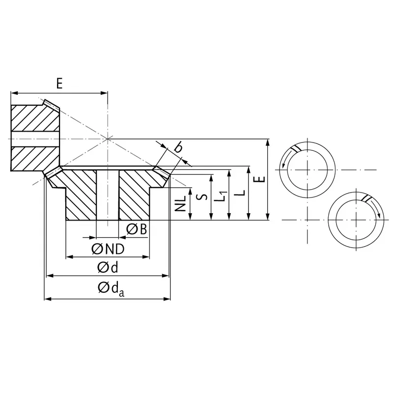
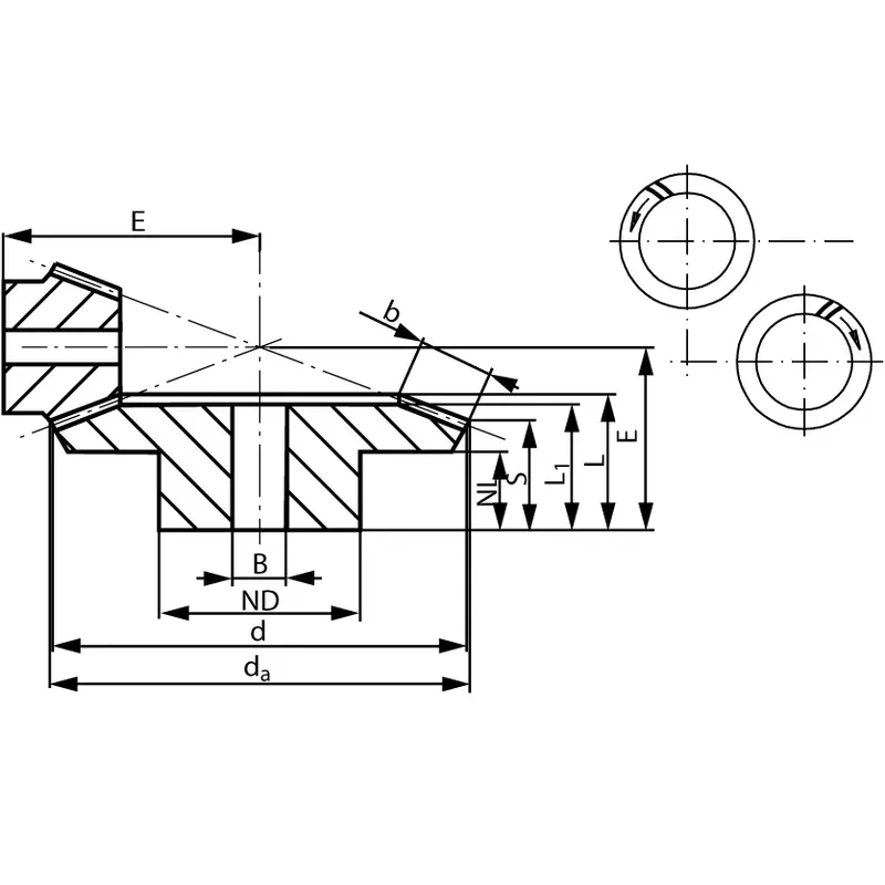
Steel spiral bevel gears with a ratio of 1:1 to 4:1 and a spiral tooth system are conical gears designed to transmit power between intersecting shafts, typically at a 90-degree angle. The spiral tooth design, with curved and angled teeth (often 35° spiral angle), ensures smoother and quieter operation compared to straight bevel gears due to gradual tooth engagement and higher contact ratios. These gears are made from high-strength carbon or alloy steels like 42CrMo4 (for modules up to 1.5) or 16MnCr5 (for modules 2.0 and above), with hardened teeth for durability. The gear ratio, calculated as the number of teeth on the driven gear divided by the pinion, ranges from 1:1 to 4:1, making them suitable for moderate speed reductions in applications like automotive differentials or industrial machinery.
Steel Spiral Bevel Gear Ratio 1:1
 |  |
| Moduł | Numer zębów | DA | D | ND | Holandia | L1 | L | S1) | B | BH7 | mi | Moment obrotowy* | Waga |
| mm | mm | mm | mm | mm | mm | mm | mm | mm | mm | Ncm | G | ||
| 0,6 | 16 | 15,8 | 15,5 | 10 | 4,5 | 9 | 10,0 | 7,7 | 3,3 | 5 | 15 | 0,64 | 12 |
| 0,6 | 20 | 16,9 | 16,5 | 12 | 6,5 | 11 | 12,0 | 9,2 | 4 | 5 | 17 | 1,27 | 19 |
| 0,6 | 25 | 23,3 | 22,5 | 19 | 7,2 | 12 | 13,4 | 9,2 | 6 | 6 | 20 | 2,1 | 50 |
| 0,6 | 30 | 27,8 | 27 | 22 | 7 | 13 | 14,9 | 9,9 | 7 | 8 | 23 | 3,0 | 75 |
| 0,6 | 35 | 32,3 | 31,5 | 25 | 7,2 | 15 | 16,3 | 10,6 | 8 | 8 | 26 | 3,5 | 116 |
| 1 | 16 | 25,4 | 24 | 17 | 7,5 | 13,5 | 15,95 | 11,7 | 6 | 6 | 23 | 2,5 | 55 |
| 1 | 20 | 31,4 | 30 | 25 | 8,4 | 15 | 17,3 | 11,7 | 8 | 8 | 26 | 6,3 | 112 |
| 1 | 25 | 38,9 | 37,5 | 25 | 8 | 16 | 19,0 | 11,9 | 10 | 10 | 30 | 10,0 | 155 |
| 1 | 30 | 46,4 | 45 | 30 | 8 | 19 | 21,7 | 13,2 | 12 | 10 | 35 | 14,3 | 278 |
| 1,3 | 20 | 41,8 | 40 | 30 | 7,3 | 19 | 20,7 | 12,9 | 11 | 10 | 32 | 14,8 | 222 |
| 1,3 | 25 | 51,8 | 50 | 30 | 8 | 19 | 21,8 | 11,9 | 14 | 10 | 36 | 18,5 | 326 |
| 1,3 | 30 | 61,8 | 60 | 35 | 8 | 21 | 24,2 | 12,9 | 16 | 12 | 42 | 31,5 | 530 |
| 1,5 | 18 | 41,7 | 39,6 | 30 | 8 | 17 | 20,3 | 13,2 | 10 | 10 | 32 | 15,9 | 209 |
| 1,5 | 24 | 54,9 | 52,8 | 35 | 8 | 20 | 22,6 | 12,7 | 14 | 10 | 38 | 21,2 | 408 |
| 1,5 | 28 | 63,7 | 61,6 | 40 | 8 | 20 | 23,2 | 13,3 | 14 | 12 | 43 | 34,5 | 576 |
| 2,2881 | 21 | 71,5 | 70 | 45 | 15 | 28 | 32,22 | 22,5 | 15 | 16 | 55 | 70 | 973 |
| 2,236 | 24 | 79,0 | 78 | 45 | 15 | 29 | 32,48 | 23,7 | 14 | 16 | 60 | 73 | 1200 |
| 2 | 26 | 82,0 | 80 | 55 | 20 | 35 | 37,73 | 26,8 | 16 | 16 | 65 | 42 | 1581 |
| 2,5 | 19 | 90,0 | 88 | 56 | 18 | 34 | 36,91 | 23,5 | 20 | 20 | 65 | 185 | 1700 |
| 2,5 | 24 | 98,0 | 96 | 54 | 16 | 32 | 37,2 | 24,5 | 19 | 20 | 70 | 188 | 2000 |
| 3 | 21 | 103,0 | 100 | 68 | 17 | 36 | 43,4 | 27,7 | 23 | 25 | 75 | 240 | 2600 |
| 3 | 24 | 115,0 | 112 | 64 | 18 | 34 | 41,7 | 26,7 | 22 | 25 | 80 | 260 | 2800 |
| 3,5 | 24 | 131,0 | 128 | 72 | 20 | 38 | 46,15 | 29,5 | 25 | 30 | 90 | 396 | 4200 |
| 3,5 | 26 | 144,0 | 140 | 85 | 30 | 57 | 62,3 | 43,0 | 28 | 30 | 110 | 238 | 7300 |
Steel Spiral Bevel Gear Ratio 1.214:1
|  |
| Moduł | Numer zębów | DA | D | ND | Holandia | L1 | L | S | B | BH7 | mi | Moment obrotowy* | Waga |
| mm | mm | mm | mm | mm | mm | mm | mm | mm | mm | Ncm | G | ||
| 1,5 | 14 | 41,0 | 38,7 | 22 | 11 | 21,1 | 24,3 | 15,4 | 11,5 | 12 | 38,0 | 14,1 | 236 |
| 1,5 | 17 | 48,9 | 47,0 | 30 | 11 | 20,9 | 23,9 | 16,6 | 11,5 | 15 | 34,8 | 17,1 | 236 |
Steel Spiral Bevel Gear Ratio 1.385:1
| |
| Moduł | Numer zębów | DA | D | ND | Holandia | L1 | L | S | B | BH7 | mi | Moment obrotowy* | Waga |
| mm | mm | mm | mm | mm | mm | mm | mm | mm | mm | Ncm | G | ||
| 1,5 | 13 | 36,7 | 33,9 | 22 | 11 | 21,6 | 24,1 | 16,0 | 10 | 12 | 38,5 | 11,3 | 216 |
| 1,5 | 18 | 48,5 | 47,0 | 30 | 11 | 20,9 | 24,7 | 18,9 | 10 | 15 | 34,8 | 15,7 | 216 |
Steel Spiral Bevel Gear Ratio 1.5:1
| |
| Moduł | Numer zębów | DA | D | ND | Holandia | L1 | L | S | B | BH7 | mi | Moment obrotowy* | Waga |
| mm | mm | mm | mm | mm | mm | mm | mm | mm | mm | Ncm | G | ||
| 0,6 | 22 | 20,8 | 19,8 | 17 | 7 | 13 | 14,3 | 8,5 | 7 | 6 | 23 | 2,2 | 116 |
| 0,6 | 33 | 30,3 | 29,7 | 20 | 8 | 14 | 15,5 | 11,6 | 7 | 8 | 21 | 3,3 | 116 |
| 1 | 20 | 31,6 | 30 | 25 | 8 | 17 | 18,3 | 10,0 | 10 | 8 | 32 | 8,1 | 166 |
| 1 | 30 | 46,3 | 45 | 30 | 8 | 17 | 19,5 | 14,0 | 10 | 10 | 28 | 12,2 | 166 |
| 1,3 | 16 | 34,3 | 32 | 25 | 8 | 18 | 19,9 | 10,7 | 11 | 8 | 34 | 11,9 | 220 |
| 1,3 | 24 | 49,4 | 48 | 30 | 8 | 18 | 21,1 | 15,0 | 11 | 10 | 30 | 17,9 | 220 |
| 1,5 | 16 | 37,8 | 35,8 | 30 | 8 | 17 | 18,8 | 10,5 | 10 | 10 | 36 | 14,3 | 273 |
| 1,5 | 24 | 54,4 | 52,8 | 35 | 8 | 17 | 21,1 | 15,6 | 10 | 10 | 32 | 21,5 | 273 |
| 2 | 16 | 53,0 | 50 | 35 | 6 | 18 | 21,37 | 12,8 | 11 | 10 | 48,45 | 41,0 | 561 |
| 2 | 24 | 76,0 | 75 | 39 | 15 | 24 | 27,53 | 21,7 | 11 | 16 | 45 | 61,5 | 561 |
| 2,5 | 16 | 67,0 | 64 | 40 | 14 | 25 | 31,89 | 19,9 | 16 | 16 | 65 | 84 | 1300 |
| 2,5 | 24 | 97,5 | 96 | 54 | 14 | 23 | 28,66 | 20,1 | 16 | 20 | 50 | 126 | 1300 |
| 3 | 16 | 79,0 | 76 | 50 | 15 | 28 | 35,71 | 21,9 | 19 | 20 | 75 | 160 | 1682 |
| 3 | 24 | 115,0 | 114 | 64 | 18 | 28 | 34,69 | 24,8 | 19 | 25 | 60 | 240 | 1682 |
Steel Spiral Bevel Gear Ratio 1.615:1
| |
| Moduł | Numer zębów | DA | D | ND | Holandia | L1 | L | S | B | BH7 | mi | Moment obrotowy* | Waga |
| mm | mm | mm | mm | mm | mm | mm | mm | mm | mm | Ncm | G | ||
| 1 | 13 | 20,8 | 18,6 | 16 | 8,2 | 12 | 13,9 | 9,3 | 5 | 8 | 24 | 2,4 | 45 |
| 1 | 21 | 30,8 | 30,0 | 20 | 6 | 10,5 | 12,0 | 9,3 | 5 | 10 | 18 | 3,9 | 45 |
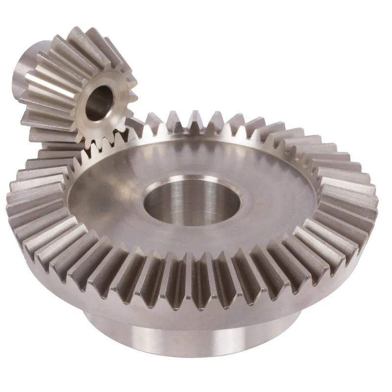
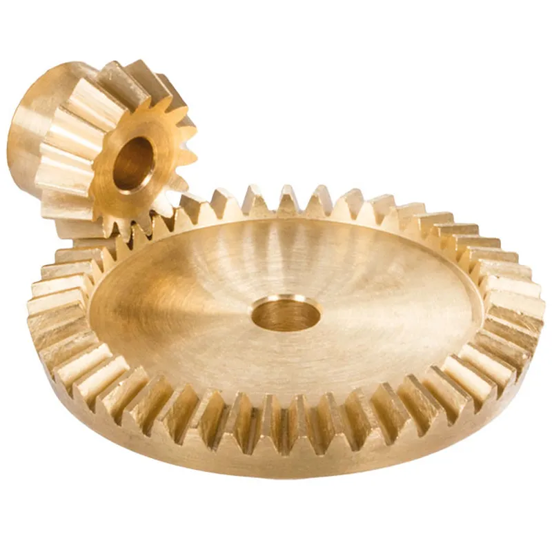
Przekładnia stożkowa spiralna ze stali o przełożeniu 2:1
 |  |
| Moduł | Numer zębów | DA | D | ND | Holandia | L1 | L | S | B | BH7 | mi | Moment obrotowy* | Waga |
| mm | mm | mm | mm | mm | mm | mm | mm | mm | mm | Ncm | G | ||
| 0,6 | 22 | 20,8 | 19,8 | 16 | 7,4 | 15 | 15,6 | 8,5 | 8 | 6 | 28 | 2,3 | 116 |
| 0,6 | 44 | 40,1 | 39,6 | 25 | 8 | 15 | 17,2 | 13,6 | 8 | 10 | 23 | 4,6 | 116 |
| 1 | 20 | 31,8 | 30 | 25 | 8 | 19 | 20,2 | 9,4 | 12 | 8 | 39 | 9,8 | 323 |
| 1 | 40 | 60,9 | 60 | 40 | 8 | 18 | 21,2 | 15,9 | 12 | 12 | 30 | 19,6 | 323 |
| 1,3 | 16 | 34,4 | 32 | 25 | 7 | 20 | 22,1 | 9,6 | 14 | 8 | 41 | 12,0 | 397 |
| 1,3 | 32 | 65,1 | 64 | 40 | 8 | 20 | 23,3 | 17,1 | 14 | 12 | 32 | 24,0 | 397 |
| 1,5 | 16 | 38,0 | 35,2 | 30 | 8,4 | 19 | 21,2 | 10,5 | 12 | 10 | 45 | 14,4 | 435 |
| 1,5 | 32 | 71,7 | 70,4 | 45 | 8 | 17 | 21,0 | 15,7 | 12 | 12 | 32 | 28,8 | 435 |
| 2,269 | 12 | 44,0 | 41,5 | 30 | 12 | 28,23 | 28,23 | 17,6 | 15 | 12 | 55 | 10,1 | 846 |
| 2,269 | 24 | 83,0 | 83 | 50 | 15 | 27 | 32,41 | 26,0 | 15 | 16 | 45 | 20,2 | 846 |
| 2,321 | 13 | 47,0 | 45 | 30 | 15 | 30 | 33,0 | 21,7 | 15 | 10 | 63,65 | 49 | 818 |
| 2,321 | 26 | 91,0 | 90 | 40 | 22 | 30 | 35,5 | 29,8 | 15 | 16 | 50 | 98 | 818 |
| 2,5 | 11 | 57,0 | 52,5 | 40 | 15 | 36,72 | 36,72 | 19,7 | 20 | 16 | 70 | 17,8 | 2000 |
| 2,5 | 22 | 106,0 | 105 | 70 | 20 | 39 | 44,65 | 35,8 | 20 | 20 | 60 | 35,6 | 2000 |
| 2,5 | 13 | 59,0 | 56 | 39 | 15 | 34 | 38,37 | 22,9 | 20 | 16 | 75,13 | 95 | 1400 |
| 2,5 | 26 | 113,0 | 112 | 54 | 21 | 30 | 37,72 | 29,0 | 20 | 25 | 55 | 190 | 1400 |
| 3 | 13 | 68,0 | 64 | 45 | 16 | 37 | 41,95 | 24,9 | 22 | 20 | 84,62 | 133 | 2000 |
| 3 | 26 | 128,0 | 128 | 54 | 20 | 32 | 39,9 | 30,6 | 22 | 25 | 60 | 266 | 2000 |
| 3 | 14 | 76,0 | 72,5 | 55 | 25 | 51,46 | 51,46 | 32,0 | 25 | 20 | 100 | 644 | 4800 |
| 3 | 28 | 146,0 | 145 | 90 | 25 | 50 | 57,1 | 46,2 | 25 | 30 | 80 | 128 | 4800 |
| 3,5 | 13 | 77,0 | 72 | 54 | 12 | 34 | 39,8 | 21,1 | 24 | 20 | 88,38 | 197 | 2800 |
| 3,5 | 26 | 146,0 | 144 | 64 | 25 | 38 | 47,1 | 36,5 | 24 | 30 | 70 | 394 | 2800 |
Steel Spiral Bevel Gear Ratio 2.066:1
| |
| Moduł | Numer zębów | DA | D | ND | Holandia | L1 | L | S | B | BH7 | mi | Moment obrotowy* | Waga |
| mm | mm | mm | mm | mm | mm | mm | mm | mm | mm | Ncm | G | ||
| 1 | 15 | 24,1 | 21,8 | 19 | 6 | 13,2 | 13,3 | 7,0 | 7 | 8 | 29,0 | 3,6 | 112 |
| 1 | 31 | 45,6 | 45,0 | 24 | 8 | 14,0 | 16,3 | 13,2 | 7 | 10 | 23,5 | 7,4 | 112 |
Steel Spiral Bevel Gear Ratio 2.5:1
| |
| Moduł | Numer zębów | DA | D | ND | Holandia | L1 | L | S | B | BH7 | mi | Moment obrotowy* | Waga |
| mm | mm | mm | mm | mm | mm | mm | mm | mm | mm | Ncm | G | ||
| 0,6 | 22 | 20,9 | 19,8 | 16 | 6,8 | 16 | 16,7 | 7,5 | 10 | 6 | 32 | 2,6 | 172 |
| 0,6 | 55 | 49,9 | 49,5 | 30 | 8 | 16 | 19,3 | 15,6 | 10 | 10 | 25 | 6,5 | 172 |
| 1,0 | 20 | 31,8 | 30 | 25 | 8,4 | 21 | 22,8 | 9,8 | 14 | 8 | 47 | 9,9 | 355 |
| 1,0 | 50 | 75,7 | 75 | 50 | 8 | 18 | 21,1 | 15,9 | 14 | 12 | 30 | 24,8 | 355 |
| 1,3 | 14 | 30,5 | 28 | 22 | 8,7 | 20 | 21,6 | 10,5 | 12 | 8 | 45 | 11,3 | 420 |
| 1,3 | 35 | 70,9 | 70 | 45 | 8 | 18 | 21,6 | 17,1 | 12 | 12 | 30 | 28,2 | 420 |
| 1,5 | 16 | 38,0 | 35,2 | 30 | 7,5 | 20 | 21,6 | 9,6 | 13 | 10 | 53 | 14,5 | 624 |
| 1,5 | 40 | 89,1 | 88 | 60 | 8 | 16 | 20,6 | 15,8 | 13 | 15 | 32 | 36,3 | 624 |
| 3,6 | 9 | 62,0 | 54,78 | 40 | 14,17 | 34 | 38,35 | 20,9 | 21 | 16 | 87,06 | 150 | 2400 |
| 3,6 | 23 | 141,0 | 140 | 70 | 35 | 45 | 52,53 | 45,0 | 21 | 30 | 70 | 383 | 2400 |
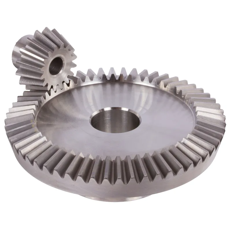
Steel Spiral Bevel Gear Ratio 3:1
 |  |
| Moduł | Numer zębów | DA | D | ND | Holandia | L1 | L | S | B | BH7 | mi | Moment obrotowy* | Waga |
| mm | mm | mm | mm | mm | mm | mm | mm | mm | mm | Ncm | G | ||
| 0,6 | 20 | 19,1 | 18 | 15 | 7,5 | 17,7 | 17,7 | 8,2 | 10 | 6 | 35 | 2,1 | 175 |
| 0,6 | 60 | 54,3 | 54 | 45 | 8 | 16 | 19,7 | 16,6 | 10 | 10 | 25 | 6,3 | 175 |
| 1 | 16 | 26,1 | 24 | 20 | 8,3 | 22 | 22,6 | 9,3 | 14 | 8 | 45 | 5,8 | 380 |
| 1 | 48 | 72,5 | 72 | 50 | 8 | 18 | 21,3 | 16,8 | 14 | 12 | 28 | 17,4 | 380 |
| 1,3 | 11 | 25,1 | 22 | 19 | 6 | 17 | 17,9 | 7,5 | 11 | 8 | 40 | 7,7 | 320 |
| 1,3 | 33 | 66,6 | 60 | 40 | 8 | 17 | 20,4 | 16,9 | 11 | 12 | 27 | 23,1 | 320 |
| 1,5 | 10 | 26,0 | 22 | 17 | 8 | 19 | 20,1 | 9,6 | 11 | 8 | 42 | 9,1 | 380 |
| 1,5 | 30 | 66,6 | 66 | 40 | 8 | 17 | 21,3 | 17,8 | 11 | 12 | 28 | 27,3 | 380 |
| 2,2291 | 9 | 36,5 | 32 | 22 | 11 | 24 | 25,8 | 15,4 | 13 | 8 | 60,52 | 28 | 638 |
| 2,2291 | 27 | 96,0 | 96 | 48 | 19 | 25 | 29,5 | 25,5 | 13 | 20 | 40 | 84 | 638 |
| 2,5736 | 9 | 42,0 | 37,5 | 27 | 12 | 26,5 | 28,64 | 15,1 | 15 | 12 | 69,84 | 46 | 1100 |
| 2,5736 | 27 | 113,0 | 112,5 | 54 | 24 | 32 | 38,41 | 33,9 | 15 | 25 | 50 | 138 | 1100 |
| 3,5 | 9 | 59,0 | 52,5 | 40 | 12 | 33 | 36,2 | 18,9 | 22 | 16 | 92,64 | 132 | 2700 |
| 3,5 | 27 | 158,5 | 157,5 | 70 | 29 | 40 | 47,9 | 41,2 | 22 | 30 | 65 | 396 | 2700 |
Przekładnia stożkowa spiralna ze stali o przełożeniu 4:1
| |
| Moduł | Numer zębów | DA | D | ND | Holandia | L1 | L | S | B | BH7 | mi | Moment obrotowy* | Waga |
| mm | mm | mm | mm | mm | mm | mm | mm | mm | mm | Ncm | G | ||
| 1 | 16 | 25,9 | 24 | 20 | 7,3 | 21 | 21,8 | 8,2 | 14 | 8 | 56 | 7,8 | 842 |
| 1 | 64 | 96,5 | 96 | 70 | 8 | 19 | 22,4 | 19 | 14 | 20 | 30 | 31,2 | 842 |
| 1,5 | 11 | 27,8 | 24,2 | 20 | 8 | 19 | 20,7 | 9 | 12 | 8 | 57 | 11,3 | 775 |
| 1,5 | 44 | 97,3 | 96,8 | 70 | 8 | 17 | 21,9 | 19 | 12 | 20 | 30 | 45,2 | 775 |
Advantages of Steel Spiral Bevel Gears
1. High Torque Capacity
Jedną z kluczowych zalet przekładni stożkowych jest ich zdolność do przenoszenia obciążeń o wysokim momencie obrotowym. Geometria i konstrukcja przekładni stożkowych umożliwiają efektywne przenoszenie mocy i momentu obrotowego między zazębiającymi się wałami.
2. Compact Design
Przekładnie stożkowe oferują kompaktowe rozwiązanie do przenoszenia mocy między wałami nierównoległymi. Dzięki zastosowaniu geometrii stożkowej, przekładnie stożkowe mogą skutecznie zmieniać kierunek obrotów w ograniczonej przestrzeni.
3. Smooth and Quiet Operation
Prawidłowo zaprojektowane i wyprodukowane przekładnie stożkowe zapewniają płynną i cichą pracę. Postęp w geometrii zębów kół zębatych, taki jak zastosowanie przekładni stożkowych o zębach spiralnych i hipoidalnych, znacznie poprawił płynność pracy i zdolność redukcji hałasu przekładni stożkowych. Zakrzywiony profil zębów przekładni stożkowych o zębach spiralnych umożliwia stopniowe zazębianie i rozprzęganie, co przekłada się na cichszą pracę w porównaniu z przekładniami stożkowymi o zębach prostych.
4. Versatility in Shaft Angles
Przekładnie stożkowe oferują elastyczność pod względem kątów nachylenia wału, jakie mogą przyjąć. Chociaż najczęstszym kątem nachylenia wału w przekładniach stożkowych jest 90 stopni, można je zaprojektować do pracy z różnymi kątami nachylenia wału.
Disadvantages of Steel Spiral Bevel Gears
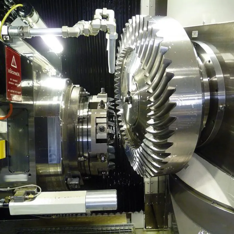
1. Higher Manufacturing Complexity
Jedną z głównych wad przekładni stożkowych jest ich większa złożoność produkcyjna w porównaniu z innymi rodzajami przekładni, takimi jak koła zębate walcowe. Produkcja przekładni stożkowych wymaga specjalistycznych maszyn i precyzyjnych procesów produkcyjnych, aby uzyskać pożądaną geometrię zębów i wykończenie powierzchni. Ta złożoność może skutkować wyższymi kosztami produkcji i dłuższym czasem realizacji.
2. Sensitivity to Misalignment
Przekładnie stożkowe są bardziej wrażliwe na niewspółosiowość niż inne rodzaje przekładni. Niewspółosiowość może prowadzić do nierównomiernego rozkładu obciążenia, zwiększonego obciążenia zębów przekładni i przedwczesnej awarii.
3. Limited Speed Capability
Przekładnie stożkowe mają ograniczenia pod względem dopuszczalnej prędkości obrotowej. Przy wysokich prędkościach przekładnie stożkowe są podatne na generowanie nadmiernego hałasu i wibracji z powodu ślizgania się zębów. Może to prowadzić do obniżenia sprawności i zwiększonego zużycia. W rezultacie przekładnie stożkowe są zazwyczaj stosowane w zastosowaniach wymagających umiarkowanych lub niskich prędkości obrotowych.
4. Higher Cost
Złożoność i precyzja produkcji wymagana w przypadku przekładni stożkowych często przekładają się na wyższe koszty w porównaniu z prostszymi typami przekładni. Potrzeba specjalistycznych maszyn, wykwalifikowanej siły roboczej i rygorystycznych środków kontroli jakości przyczynia się do wzrostu kosztów przekładni stożkowych. Ponadto, wymagania dotyczące personalizacji i specyficznej konstrukcji przekładni stożkowych dla konkretnych zastosowań mogą dodatkowo zwiększyć ich koszt.
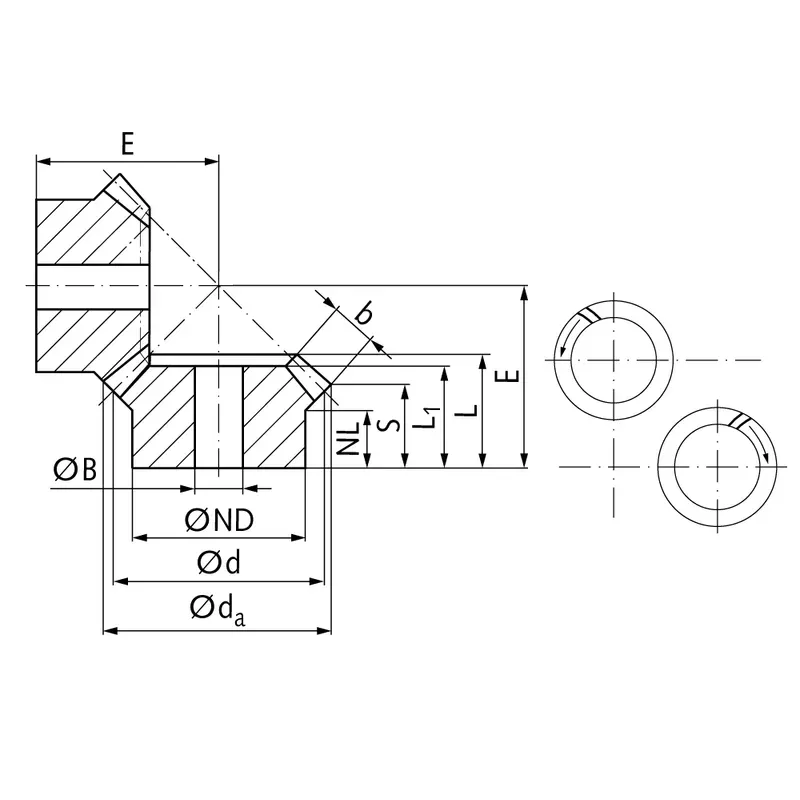
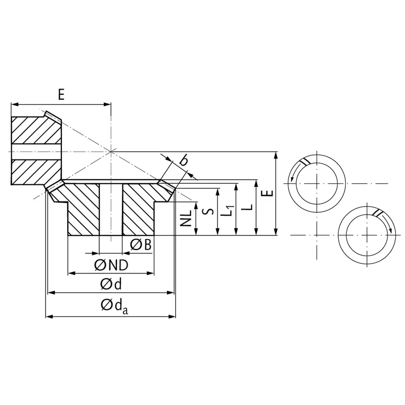
Key Dimensions & Angles of Bevel Gears
Bevel gears are complex mechanical components characterized by a range of critical dimensions and angles.
A. Detailed Examination of Basic Dimensions
Several key dimensions define the overall geometry and size of a bevel gear:
- Pitch Diameter: This diameter is measured at the heel end of the bevel gear teeth. It represents the effective size of the gear and is a fundamental parameter for gear calculations and design.
- Pitch Cone Angle: The pitch cone angle describes the angle formed by the pitch cone relative to the gear axis. It defines the orientation of the gear teeth and determines how the gear meshes with its mating pinion.
- Addendum & Dedendum: The addendum is the height of the gear tooth above the pitch cone, while the dedendum is the depth below it. Together, they define the total tooth depth. The addendum and dedendum are typically specified in proportion to the gear module.
- Face Width: Face width refers to the size of the gear tooth measured along the pitch cone generatrix from the heel to the toe. It affects gear tooth strength and load capacity. Wider face widths generally allow greater torque transmission.
- Cone Distance: The cone distance represents the length from the apex of the pitch cone to the mid-face of the bevel gear. It is a key dimension for positioning the gear relative to its mating pinion during assembly.
- Vertex Distance: Vertex distance measures the offset from the gear axis to the pitch cone apex. It helps locate the theoretical point of mesh between gears.
B. Essential Bevel Gear Angles
In addition to linear dimensions, several angles are critical in defining a bevel gear’s geometry:
- Kąt twarzy: The angle between the face cone generatrix and the gear axis. It determines the angle of the outer ends of the gear teeth relative to the rotational axis.
- Edge Angle: Measured between the outer cone generatrix and gear axis, the edge angle defines the slope of the inner ends of the teeth nearest the apex.
- Addendum Angle: This is the angular equivalent of the addendum, defining the tooth height in angular terms from the face angle to the outside edge.
- Dedendum Angle: Correspondingly, the dedendum angle measures the angular tooth depth from the pitch line down to the tooth root.
C. Backlash
Backlash refers to the clearance or play between the teeth of two meshing gears. Some backlash is necessary to accommodate lubrication, manufacturing tolerances, and thermal expansion. However, excessive backlash can cause noise, vibration, and imprecise positioning. Backlash is typically measured at the tightest point of mesh using dedicated tools or by assessing the angular play with the gears held fixed.
D. Module
The module of a gear is a standardized unit that indicates tooth size. It is defined as the ratio of the pitch diameter to the number of teeth. In bevel gears, the module is typically specified at the heel end for manufacturing purposes. Larger module numbers correspond to bigger, coarser teeth, while finer pitch gears have smaller modules.
Informacje dodatkowe
| Edytowane przez | Yjx |
|---|
Podobne produkty
-
Przekładnie stożkowe spiralne ze stali o stosunku zębów 2,066:1
-
Przekładnie stożkowe ze stali nierdzewnej o stosunku 1:1 i zębach prostych
-
Steel Straight Bevel Gears Ratio 1:1 – 4:1 Straight Tooth System
-
Przekładnie stożkowe mosiężne o przełożeniu 2:1, układ zębów prostych
-
Przekładnie stożkowe mosiężne o przełożeniu 2,5:1, układ zębów prostych


