Nisbah Gear Serong Spiral Keluli 1:1 – 4:1 Sistem Gigi Spiral
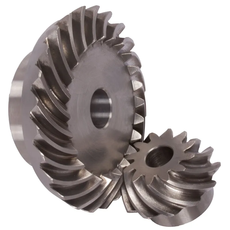
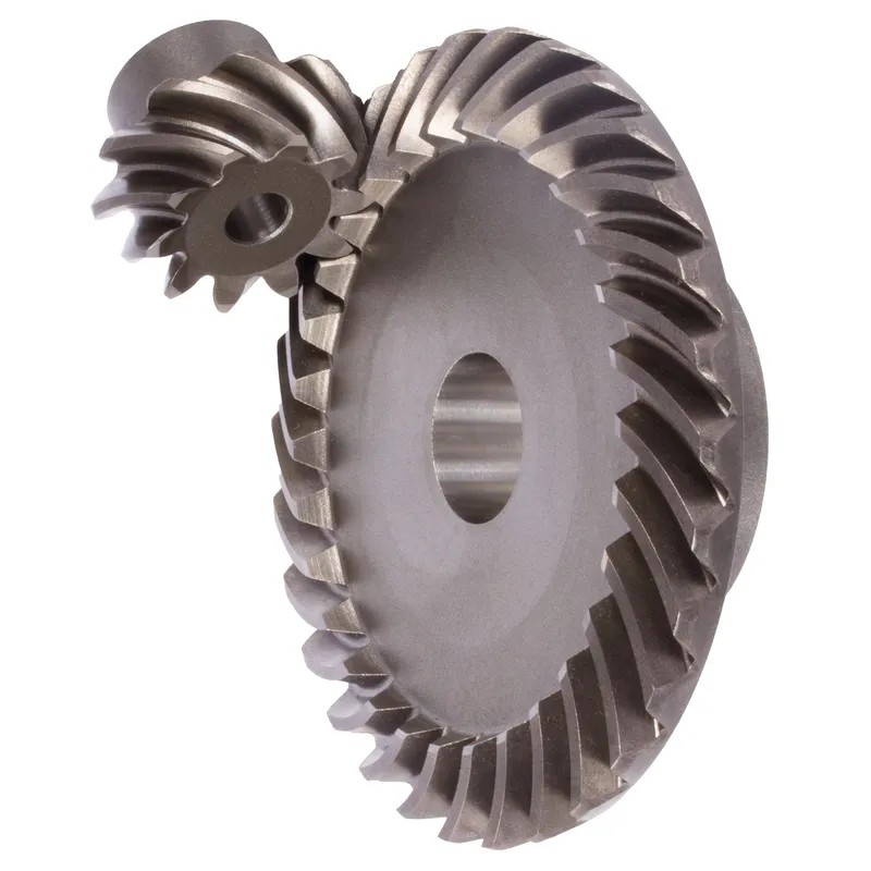
Steel spiral bevel gears with a ratio of 1.2:1 to 1.6:1 and a spiral tooth system are conical gears designed to transmit power between intersecting shafts, typically at a 90-degree angle. The spiral tooth design, with curved and angled teeth (often 35° spiral angle), ensures smoother and quieter operation compared to straight bevel gears due to gradual tooth engagement and higher contact ratios. These steel bevel gears are made from high-strength carbon or alloy steels like 42CrMo4 or 16MnCr5, suitable for moderate speed reductions in applications like automotive differentials or industrial machinery.
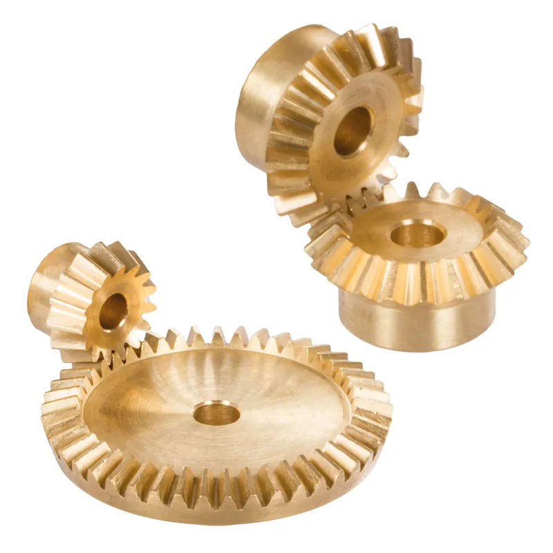
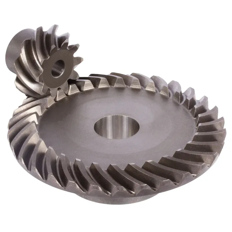
Steel spiral bevel gears with a ratio of 1:1 to 4:1 and a spiral tooth system are conical gears designed to transmit power between intersecting shafts, typically at a 90-degree angle. The spiral tooth design, with curved and angled teeth (often 35° spiral angle), ensures smoother and quieter operation compared to straight bevel gears due to gradual tooth engagement and higher contact ratios. These gears are made from high-strength carbon or alloy steels like 42CrMo4 (for modules up to 1.5) or 16MnCr5 (for modules 2.0 and above), with hardened teeth for durability. The gear ratio, calculated as the number of teeth on the driven gear divided by the pinion, ranges from 1:1 to 4:1, making them suitable for moderate speed reductions in applications like automotive differentials or industrial machinery.
Steel Spiral Bevel Gear Ratio 1:1
 | 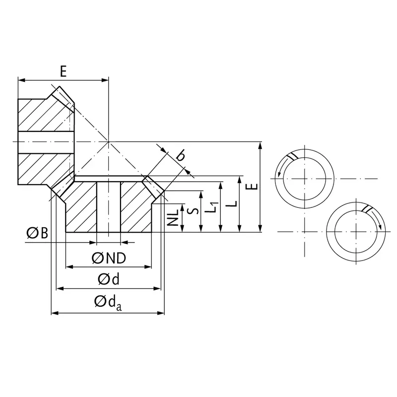 |
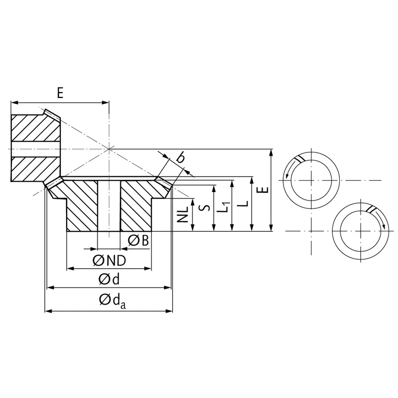
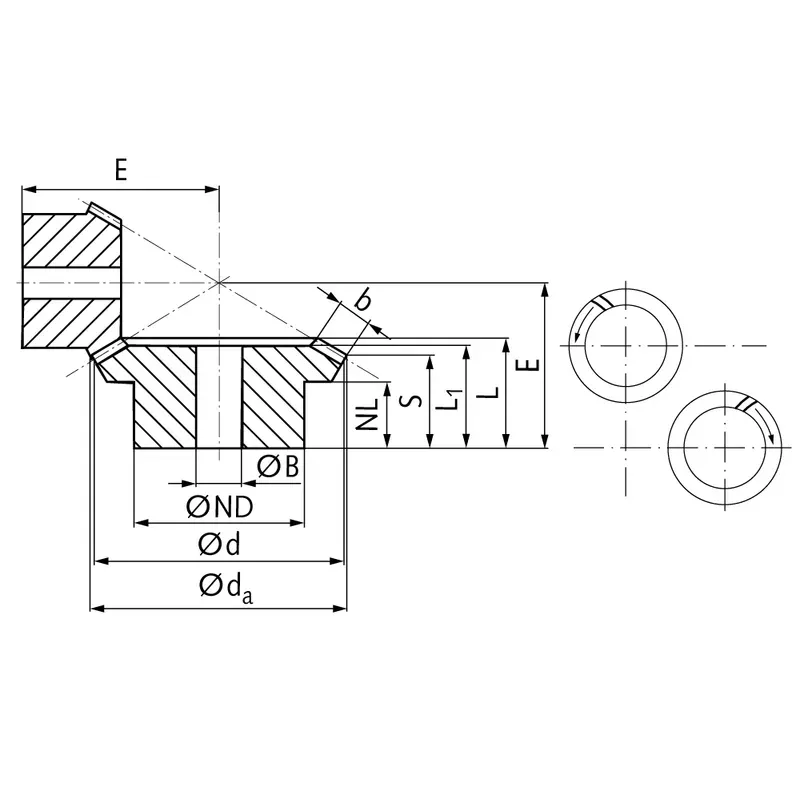
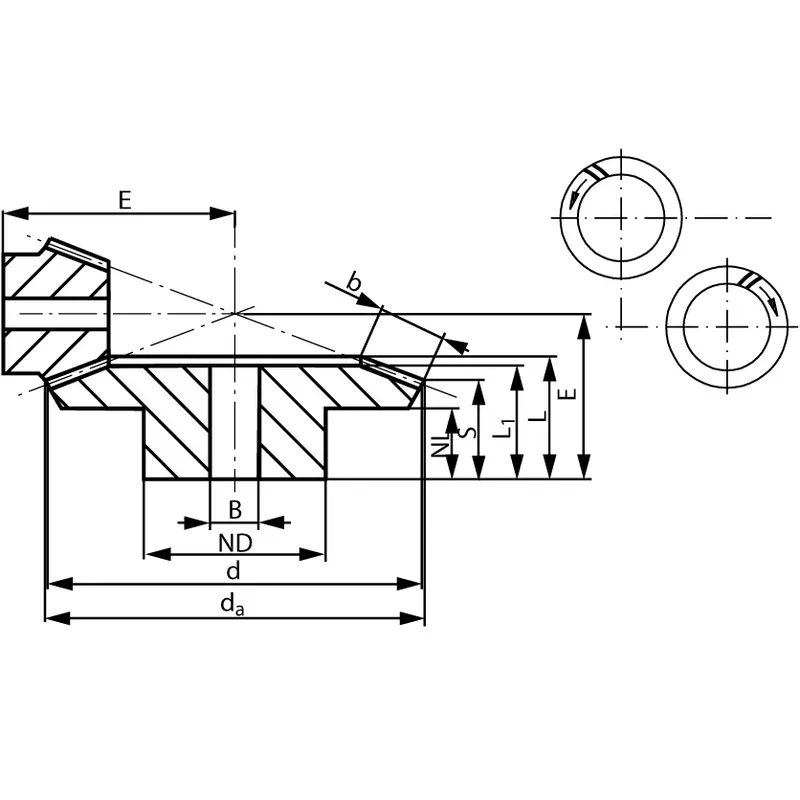
| Modul | Nombor gigi | dseorang | d | ND | NL | L1 | L | S1) | b | BH7 | E | Tork* | Berat |
| mm | mm | mm | mm | mm | mm | mm | mm | mm | mm | Ncm | g | ||
| 0,6 | 16 | 15,8 | 15,5 | 10 | 4,5 | 9 | 10,0 | 7,7 | 3,3 | 5 | 15 | 0,64 | 12 |
| 0,6 | 20 | 16,9 | 16,5 | 12 | 6,5 | 11 | 12,0 | 9,2 | 4 | 5 | 17 | 1,27 | 19 |
| 0,6 | 25 | 23,3 | 22,5 | 19 | 7,2 | 12 | 13,4 | 9,2 | 6 | 6 | 20 | 2,1 | 50 |
| 0,6 | 30 | 27,8 | 27 | 22 | 7 | 13 | 14,9 | 9,9 | 7 | 8 | 23 | 3,0 | 75 |
| 0,6 | 35 | 32,3 | 31,5 | 25 | 7,2 | 15 | 16,3 | 10,6 | 8 | 8 | 26 | 3,5 | 116 |
| 1 | 16 | 25,4 | 24 | 17 | 7,5 | 13,5 | 15,95 | 11,7 | 6 | 6 | 23 | 2,5 | 55 |
| 1 | 20 | 31,4 | 30 | 25 | 8,4 | 15 | 17,3 | 11,7 | 8 | 8 | 26 | 6,3 | 112 |
| 1 | 25 | 38,9 | 37,5 | 25 | 8 | 16 | 19,0 | 11,9 | 10 | 10 | 30 | 10,0 | 155 |
| 1 | 30 | 46,4 | 45 | 30 | 8 | 19 | 21,7 | 13,2 | 12 | 10 | 35 | 14,3 | 278 |
| 1,3 | 20 | 41,8 | 40 | 30 | 7,3 | 19 | 20,7 | 12,9 | 11 | 10 | 32 | 14,8 | 222 |
| 1,3 | 25 | 51,8 | 50 | 30 | 8 | 19 | 21,8 | 11,9 | 14 | 10 | 36 | 18,5 | 326 |
| 1,3 | 30 | 61,8 | 60 | 35 | 8 | 21 | 24,2 | 12,9 | 16 | 12 | 42 | 31,5 | 530 |
| 1,5 | 18 | 41,7 | 39,6 | 30 | 8 | 17 | 20,3 | 13,2 | 10 | 10 | 32 | 15,9 | 209 |
| 1,5 | 24 | 54,9 | 52,8 | 35 | 8 | 20 | 22,6 | 12,7 | 14 | 10 | 38 | 21,2 | 408 |
| 1,5 | 28 | 63,7 | 61,6 | 40 | 8 | 20 | 23,2 | 13,3 | 14 | 12 | 43 | 34,5 | 576 |
| 2,2881 | 21 | 71,5 | 70 | 45 | 15 | 28 | 32,22 | 22,5 | 15 | 16 | 55 | 70 | 973 |
| 2,236 | 24 | 79,0 | 78 | 45 | 15 | 29 | 32,48 | 23,7 | 14 | 16 | 60 | 73 | 1200 |
| 2 | 26 | 82,0 | 80 | 55 | 20 | 35 | 37,73 | 26,8 | 16 | 16 | 65 | 42 | 1581 |
| 2,5 | 19 | 90,0 | 88 | 56 | 18 | 34 | 36,91 | 23,5 | 20 | 20 | 65 | 185 | 1700 |
| 2,5 | 24 | 98,0 | 96 | 54 | 16 | 32 | 37,2 | 24,5 | 19 | 20 | 70 | 188 | 2000 |
| 3 | 21 | 103,0 | 100 | 68 | 17 | 36 | 43,4 | 27,7 | 23 | 25 | 75 | 240 | 2600 |
| 3 | 24 | 115,0 | 112 | 64 | 18 | 34 | 41,7 | 26,7 | 22 | 25 | 80 | 260 | 2800 |
| 3,5 | 24 | 131,0 | 128 | 72 | 20 | 38 | 46,15 | 29,5 | 25 | 30 | 90 | 396 | 4200 |
| 3,5 | 26 | 144,0 | 140 | 85 | 30 | 57 | 62,3 | 43,0 | 28 | 30 | 110 | 238 | 7300 |
Steel Spiral Bevel Gear Ratio 1.214:1
|  |
| Modul | Nombor gigi | dseorang | d | ND | NL | L1 | L | S | b | BH7 | E | Tork* | Berat |
| mm | mm | mm | mm | mm | mm | mm | mm | mm | mm | Ncm | g | ||
| 1,5 | 14 | 41,0 | 38,7 | 22 | 11 | 21,1 | 24,3 | 15,4 | 11,5 | 12 | 38,0 | 14,1 | 236 |
| 1,5 | 17 | 48,9 | 47,0 | 30 | 11 | 20,9 | 23,9 | 16,6 | 11,5 | 15 | 34,8 | 17,1 | 236 |
Steel Spiral Bevel Gear Ratio 1.385:1
| |
| Modul | Nombor gigi | dseorang | d | ND | NL | L1 | L | S | b | BH7 | E | Tork* | Berat |
| mm | mm | mm | mm | mm | mm | mm | mm | mm | mm | Ncm | g | ||
| 1,5 | 13 | 36,7 | 33,9 | 22 | 11 | 21,6 | 24,1 | 16,0 | 10 | 12 | 38,5 | 11,3 | 216 |
| 1,5 | 18 | 48,5 | 47,0 | 30 | 11 | 20,9 | 24,7 | 18,9 | 10 | 15 | 34,8 | 15,7 | 216 |
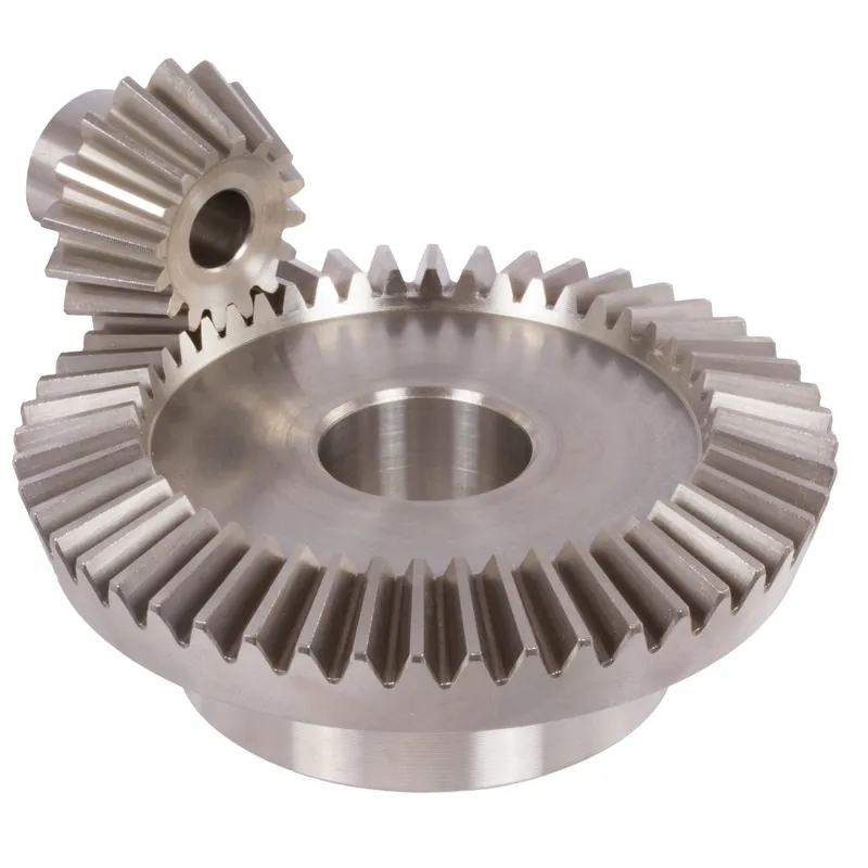
Steel Spiral Bevel Gear Ratio 1.5:1
| |
| Modul | Nombor gigi | dseorang | d | ND | NL | L1 | L | S | b | BH7 | E | Tork* | Berat |
| mm | mm | mm | mm | mm | mm | mm | mm | mm | mm | Ncm | g | ||
| 0,6 | 22 | 20,8 | 19,8 | 17 | 7 | 13 | 14,3 | 8,5 | 7 | 6 | 23 | 2,2 | 116 |
| 0,6 | 33 | 30,3 | 29,7 | 20 | 8 | 14 | 15,5 | 11,6 | 7 | 8 | 21 | 3,3 | 116 |
| 1 | 20 | 31,6 | 30 | 25 | 8 | 17 | 18,3 | 10,0 | 10 | 8 | 32 | 8,1 | 166 |
| 1 | 30 | 46,3 | 45 | 30 | 8 | 17 | 19,5 | 14,0 | 10 | 10 | 28 | 12,2 | 166 |
| 1,3 | 16 | 34,3 | 32 | 25 | 8 | 18 | 19,9 | 10,7 | 11 | 8 | 34 | 11,9 | 220 |
| 1,3 | 24 | 49,4 | 48 | 30 | 8 | 18 | 21,1 | 15,0 | 11 | 10 | 30 | 17,9 | 220 |
| 1,5 | 16 | 37,8 | 35,8 | 30 | 8 | 17 | 18,8 | 10,5 | 10 | 10 | 36 | 14,3 | 273 |
| 1,5 | 24 | 54,4 | 52,8 | 35 | 8 | 17 | 21,1 | 15,6 | 10 | 10 | 32 | 21,5 | 273 |
| 2 | 16 | 53,0 | 50 | 35 | 6 | 18 | 21,37 | 12,8 | 11 | 10 | 48,45 | 41,0 | 561 |
| 2 | 24 | 76,0 | 75 | 39 | 15 | 24 | 27,53 | 21,7 | 11 | 16 | 45 | 61,5 | 561 |
| 2,5 | 16 | 67,0 | 64 | 40 | 14 | 25 | 31,89 | 19,9 | 16 | 16 | 65 | 84 | 1300 |
| 2,5 | 24 | 97,5 | 96 | 54 | 14 | 23 | 28,66 | 20,1 | 16 | 20 | 50 | 126 | 1300 |
| 3 | 16 | 79,0 | 76 | 50 | 15 | 28 | 35,71 | 21,9 | 19 | 20 | 75 | 160 | 1682 |
| 3 | 24 | 115,0 | 114 | 64 | 18 | 28 | 34,69 | 24,8 | 19 | 25 | 60 | 240 | 1682 |
Steel Spiral Bevel Gear Ratio 1.615:1
| |
| Modul | Nombor gigi | dseorang | d | ND | NL | L1 | L | S | b | BH7 | E | Tork* | Berat |
| mm | mm | mm | mm | mm | mm | mm | mm | mm | mm | Ncm | g | ||
| 1 | 13 | 20,8 | 18,6 | 16 | 8,2 | 12 | 13,9 | 9,3 | 5 | 8 | 24 | 2,4 | 45 |
| 1 | 21 | 30,8 | 30,0 | 20 | 6 | 10,5 | 12,0 | 9,3 | 5 | 10 | 18 | 3,9 | 45 |
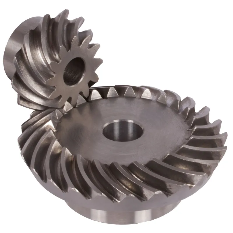
Steel Spiral Bevel Gear Ratio 2:1
 |  |
| Modul | Nombor gigi | dseorang | d | ND | NL | L1 | L | S | b | BH7 | E | Tork* | Berat |
| mm | mm | mm | mm | mm | mm | mm | mm | mm | mm | Ncm | g | ||
| 0,6 | 22 | 20,8 | 19,8 | 16 | 7,4 | 15 | 15,6 | 8,5 | 8 | 6 | 28 | 2,3 | 116 |
| 0,6 | 44 | 40,1 | 39,6 | 25 | 8 | 15 | 17,2 | 13,6 | 8 | 10 | 23 | 4,6 | 116 |
| 1 | 20 | 31,8 | 30 | 25 | 8 | 19 | 20,2 | 9,4 | 12 | 8 | 39 | 9,8 | 323 |
| 1 | 40 | 60,9 | 60 | 40 | 8 | 18 | 21,2 | 15,9 | 12 | 12 | 30 | 19,6 | 323 |
| 1,3 | 16 | 34,4 | 32 | 25 | 7 | 20 | 22,1 | 9,6 | 14 | 8 | 41 | 12,0 | 397 |
| 1,3 | 32 | 65,1 | 64 | 40 | 8 | 20 | 23,3 | 17,1 | 14 | 12 | 32 | 24,0 | 397 |
| 1,5 | 16 | 38,0 | 35,2 | 30 | 8,4 | 19 | 21,2 | 10,5 | 12 | 10 | 45 | 14,4 | 435 |
| 1,5 | 32 | 71,7 | 70,4 | 45 | 8 | 17 | 21,0 | 15,7 | 12 | 12 | 32 | 28,8 | 435 |
| 2,269 | 12 | 44,0 | 41,5 | 30 | 12 | 28,23 | 28,23 | 17,6 | 15 | 12 | 55 | 10,1 | 846 |
| 2,269 | 24 | 83,0 | 83 | 50 | 15 | 27 | 32,41 | 26,0 | 15 | 16 | 45 | 20,2 | 846 |
| 2,321 | 13 | 47,0 | 45 | 30 | 15 | 30 | 33,0 | 21,7 | 15 | 10 | 63,65 | 49 | 818 |
| 2,321 | 26 | 91,0 | 90 | 40 | 22 | 30 | 35,5 | 29,8 | 15 | 16 | 50 | 98 | 818 |
| 2,5 | 11 | 57,0 | 52,5 | 40 | 15 | 36,72 | 36,72 | 19,7 | 20 | 16 | 70 | 17,8 | 2000 |
| 2,5 | 22 | 106,0 | 105 | 70 | 20 | 39 | 44,65 | 35,8 | 20 | 20 | 60 | 35,6 | 2000 |
| 2,5 | 13 | 59,0 | 56 | 39 | 15 | 34 | 38,37 | 22,9 | 20 | 16 | 75,13 | 95 | 1400 |
| 2,5 | 26 | 113,0 | 112 | 54 | 21 | 30 | 37,72 | 29,0 | 20 | 25 | 55 | 190 | 1400 |
| 3 | 13 | 68,0 | 64 | 45 | 16 | 37 | 41,95 | 24,9 | 22 | 20 | 84,62 | 133 | 2000 |
| 3 | 26 | 128,0 | 128 | 54 | 20 | 32 | 39,9 | 30,6 | 22 | 25 | 60 | 266 | 2000 |
| 3 | 14 | 76,0 | 72,5 | 55 | 25 | 51,46 | 51,46 | 32,0 | 25 | 20 | 100 | 644 | 4800 |
| 3 | 28 | 146,0 | 145 | 90 | 25 | 50 | 57,1 | 46,2 | 25 | 30 | 80 | 128 | 4800 |
| 3,5 | 13 | 77,0 | 72 | 54 | 12 | 34 | 39,8 | 21,1 | 24 | 20 | 88,38 | 197 | 2800 |
| 3,5 | 26 | 146,0 | 144 | 64 | 25 | 38 | 47,1 | 36,5 | 24 | 30 | 70 | 394 | 2800 |
Steel Spiral Bevel Gear Ratio 2.066:1
| |
| Modul | Nombor gigi | dseorang | d | ND | NL | L1 | L | S | b | BH7 | E | Tork* | Berat |
| mm | mm | mm | mm | mm | mm | mm | mm | mm | mm | Ncm | g | ||
| 1 | 15 | 24,1 | 21,8 | 19 | 6 | 13,2 | 13,3 | 7,0 | 7 | 8 | 29,0 | 3,6 | 112 |
| 1 | 31 | 45,6 | 45,0 | 24 | 8 | 14,0 | 16,3 | 13,2 | 7 | 10 | 23,5 | 7,4 | 112 |
Steel Spiral Bevel Gear Ratio 2.5:1
| |
| Modul | Nombor gigi | dseorang | d | ND | NL | L1 | L | S | b | BH7 | E | Tork* | Berat |
| mm | mm | mm | mm | mm | mm | mm | mm | mm | mm | Ncm | g | ||
| 0,6 | 22 | 20,9 | 19,8 | 16 | 6,8 | 16 | 16,7 | 7,5 | 10 | 6 | 32 | 2,6 | 172 |
| 0,6 | 55 | 49,9 | 49,5 | 30 | 8 | 16 | 19,3 | 15,6 | 10 | 10 | 25 | 6,5 | 172 |
| 1,0 | 20 | 31,8 | 30 | 25 | 8,4 | 21 | 22,8 | 9,8 | 14 | 8 | 47 | 9,9 | 355 |
| 1,0 | 50 | 75,7 | 75 | 50 | 8 | 18 | 21,1 | 15,9 | 14 | 12 | 30 | 24,8 | 355 |
| 1,3 | 14 | 30,5 | 28 | 22 | 8,7 | 20 | 21,6 | 10,5 | 12 | 8 | 45 | 11,3 | 420 |
| 1,3 | 35 | 70,9 | 70 | 45 | 8 | 18 | 21,6 | 17,1 | 12 | 12 | 30 | 28,2 | 420 |
| 1,5 | 16 | 38,0 | 35,2 | 30 | 7,5 | 20 | 21,6 | 9,6 | 13 | 10 | 53 | 14,5 | 624 |
| 1,5 | 40 | 89,1 | 88 | 60 | 8 | 16 | 20,6 | 15,8 | 13 | 15 | 32 | 36,3 | 624 |
| 3,6 | 9 | 62,0 | 54,78 | 40 | 14,17 | 34 | 38,35 | 20,9 | 21 | 16 | 87,06 | 150 | 2400 |
| 3,6 | 23 | 141,0 | 140 | 70 | 35 | 45 | 52,53 | 45,0 | 21 | 30 | 70 | 383 | 2400 |
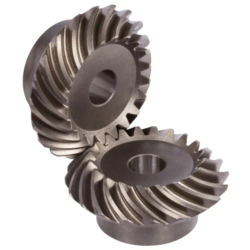
Steel Spiral Bevel Gear Ratio 3:1
 |  |
| Modul | Nombor gigi | dseorang | d | ND | NL | L1 | L | S | b | BH7 | E | Tork* | Berat |
| mm | mm | mm | mm | mm | mm | mm | mm | mm | mm | Ncm | g | ||
| 0,6 | 20 | 19,1 | 18 | 15 | 7,5 | 17,7 | 17,7 | 8,2 | 10 | 6 | 35 | 2,1 | 175 |
| 0,6 | 60 | 54,3 | 54 | 45 | 8 | 16 | 19,7 | 16,6 | 10 | 10 | 25 | 6,3 | 175 |
| 1 | 16 | 26,1 | 24 | 20 | 8,3 | 22 | 22,6 | 9,3 | 14 | 8 | 45 | 5,8 | 380 |
| 1 | 48 | 72,5 | 72 | 50 | 8 | 18 | 21,3 | 16,8 | 14 | 12 | 28 | 17,4 | 380 |
| 1,3 | 11 | 25,1 | 22 | 19 | 6 | 17 | 17,9 | 7,5 | 11 | 8 | 40 | 7,7 | 320 |
| 1,3 | 33 | 66,6 | 60 | 40 | 8 | 17 | 20,4 | 16,9 | 11 | 12 | 27 | 23,1 | 320 |
| 1,5 | 10 | 26,0 | 22 | 17 | 8 | 19 | 20,1 | 9,6 | 11 | 8 | 42 | 9,1 | 380 |
| 1,5 | 30 | 66,6 | 66 | 40 | 8 | 17 | 21,3 | 17,8 | 11 | 12 | 28 | 27,3 | 380 |
| 2,2291 | 9 | 36,5 | 32 | 22 | 11 | 24 | 25,8 | 15,4 | 13 | 8 | 60,52 | 28 | 638 |
| 2,2291 | 27 | 96,0 | 96 | 48 | 19 | 25 | 29,5 | 25,5 | 13 | 20 | 40 | 84 | 638 |
| 2,5736 | 9 | 42,0 | 37,5 | 27 | 12 | 26,5 | 28,64 | 15,1 | 15 | 12 | 69,84 | 46 | 1100 |
| 2,5736 | 27 | 113,0 | 112,5 | 54 | 24 | 32 | 38,41 | 33,9 | 15 | 25 | 50 | 138 | 1100 |
| 3,5 | 9 | 59,0 | 52,5 | 40 | 12 | 33 | 36,2 | 18,9 | 22 | 16 | 92,64 | 132 | 2700 |
| 3,5 | 27 | 158,5 | 157,5 | 70 | 29 | 40 | 47,9 | 41,2 | 22 | 30 | 65 | 396 | 2700 |
Nisbah Gear Serong Lingkaran Keluli 4:1
| |
| Modul | Nombor gigi | dseorang | d | ND | NL | L1 | L | S | b | BH7 | E | Tork* | Berat |
| mm | mm | mm | mm | mm | mm | mm | mm | mm | mm | Ncm | g | ||
| 1 | 16 | 25,9 | 24 | 20 | 7,3 | 21 | 21,8 | 8,2 | 14 | 8 | 56 | 7,8 | 842 |
| 1 | 64 | 96,5 | 96 | 70 | 8 | 19 | 22,4 | 19 | 14 | 20 | 30 | 31,2 | 842 |
| 1,5 | 11 | 27,8 | 24,2 | 20 | 8 | 19 | 20,7 | 9 | 12 | 8 | 57 | 11,3 | 775 |
| 1,5 | 44 | 97,3 | 96,8 | 70 | 8 | 17 | 21,9 | 19 | 12 | 20 | 30 | 45,2 | 775 |
Advantages of Steel Spiral Bevel Gears
1. High Torque Capacity
Salah satu kelebihan utama gear serong ialah keupayaannya untuk mengendalikan beban tork yang tinggi. Geometri dan reka bentuk gear serong membolehkan penghantaran kuasa dan tork yang cekap antara aci yang bersilang.
2. Compact Design
Gear serong menawarkan penyelesaian padat untuk penghantaran kuasa antara aci bukan selari. Dengan menggunakan geometri kon, gear serong boleh mengubah arah putaran secara berkesan dalam ruang terhad.
3. Smooth and Quiet Operation
Apabila direka bentuk dan dihasilkan dengan betul, gear serong boleh memberikan operasi yang lancar dan senyap. Kemajuan dalam geometri gigi gear, seperti penggunaan gear serong lingkaran dan gear hipoid, telah meningkatkan keupayaan kelancaran dan pengurangan hingar gear serong dengan ketara. Profil gigi melengkung gear serong lingkaran membolehkan penglibatan dan pelepasan secara beransur-ansur, menghasilkan operasi yang lebih senyap berbanding gear serong lurus.
4. Versatility in Shaft Angles
Gear serong menawarkan fleksibiliti dari segi sudut aci yang boleh ditampungnya. Walaupun sudut aci yang paling biasa untuk gear serong ialah 90 darjah, ia boleh direka bentuk untuk berfungsi dengan pelbagai sudut aci.
Disadvantages of Steel Spiral Bevel Gears
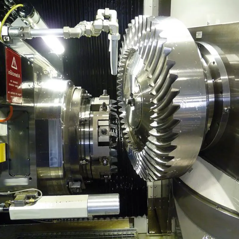
1. Higher Manufacturing Complexity
Salah satu kelemahan utama gear serong ialah kerumitan pembuatannya yang lebih tinggi berbanding jenis gear lain, seperti gear taji. Pengeluaran gear serong memerlukan jentera khusus dan proses pembuatan yang tepat untuk mencapai geometri gigi dan kemasan permukaan yang diingini. Kerumitan ini boleh mengakibatkan peningkatan kos pembuatan dan masa tunggu yang lebih lama.
2. Sensitivity to Misalignment
Gear serong lebih sensitif terhadap ketidaksejajaran berbanding jenis gear lain. Ketidaksejajaran boleh menyebabkan pengagihan beban yang tidak sekata, peningkatan tekanan pada gigi gear dan kegagalan pramatang.
3. Limited Speed Capability
Gear serong mempunyai batasan dari segi keupayaan kelajuannya. Pada kelajuan tinggi, gear serong terdedah kepada bunyi bising dan getaran yang berlebihan disebabkan oleh tindakan gelongsor antara gigi gear. Ini boleh menyebabkan kecekapan yang berkurangan dan haus yang meningkat. Akibatnya, gear serong biasanya digunakan dalam aplikasi dengan keperluan kelajuan sederhana hingga rendah.
4. Higher Cost
Kerumitan dan ketepatan pembuatan yang diperlukan untuk gear serong selalunya diterjemahkan kepada kos yang lebih tinggi berbanding jenis gear yang lebih mudah. Keperluan untuk jentera khusus, buruh mahir dan langkah kawalan kualiti yang ketat menyumbang kepada peningkatan kos gear serong. Di samping itu, penyesuaian dan keperluan reka bentuk khusus gear serong untuk aplikasi tertentu boleh meningkatkan lagi kosnya.
Key Dimensions & Angles of Bevel Gears
Bevel gears are complex mechanical components characterized by a range of critical dimensions and angles.
A. Detailed Examination of Basic Dimensions
Several key dimensions define the overall geometry and size of a bevel gear:
- Pitch Diameter: This diameter is measured at the heel end of the bevel gear teeth. It represents the effective size of the gear and is a fundamental parameter for gear calculations and design.
- Pitch Cone Angle: The pitch cone angle describes the angle formed by the pitch cone relative to the gear axis. It defines the orientation of the gear teeth and determines how the gear meshes with its mating pinion.
- Addendum & Dedendum: The addendum is the height of the gear tooth above the pitch cone, while the dedendum is the depth below it. Together, they define the total tooth depth. The addendum and dedendum are typically specified in proportion to the gear module.
- Face Width: Face width refers to the size of the gear tooth measured along the pitch cone generatrix from the heel to the toe. It affects gear tooth strength and load capacity. Wider face widths generally allow greater torque transmission.
- Cone Distance: The cone distance represents the length from the apex of the pitch cone to the mid-face of the bevel gear. It is a key dimension for positioning the gear relative to its mating pinion during assembly.
- Vertex Distance: Vertex distance measures the offset from the gear axis to the pitch cone apex. It helps locate the theoretical point of mesh between gears.
B. Essential Bevel Gear Angles
In addition to linear dimensions, several angles are critical in defining a bevel gear’s geometry:
- Sudut Muka: The angle between the face cone generatrix and the gear axis. It determines the angle of the outer ends of the gear teeth relative to the rotational axis.
- Edge Angle: Measured between the outer cone generatrix and gear axis, the edge angle defines the slope of the inner ends of the teeth nearest the apex.
- Addendum Angle: This is the angular equivalent of the addendum, defining the tooth height in angular terms from the face angle to the outside edge.
- Dedendum Angle: Correspondingly, the dedendum angle measures the angular tooth depth from the pitch line down to the tooth root.
C. Backlash
Backlash refers to the clearance or play between the teeth of two meshing gears. Some backlash is necessary to accommodate lubrication, manufacturing tolerances, and thermal expansion. However, excessive backlash can cause noise, vibration, and imprecise positioning. Backlash is typically measured at the tightest point of mesh using dedicated tools or by assessing the angular play with the gears held fixed.
D. Module
The module of a gear is a standardized unit that indicates tooth size. It is defined as the ratio of the pitch diameter to the number of teeth. In bevel gears, the module is typically specified at the heel end for manufacturing purposes. Larger module numbers correspond to bigger, coarser teeth, while finer pitch gears have smaller modules.
Maklumat tambahan
| Disunting oleh | Yjx |
|---|