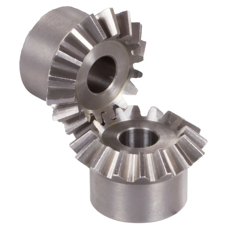
Ingranaggi conici in acciaio inossidabile con rapporto 4:1, sistema a denti dritti
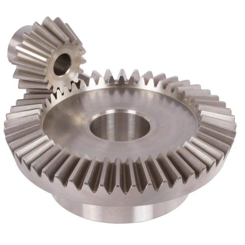
The stainless steel bevel gears ratio 4:1 straight-tooth system is a mechanical gear setup designed for efficient power transmission between two intersecting shafts, typically at a right angle (90°). These bevel gears are made of durable stainless steel, offering excellent resistance to corrosion, wear, and high-temperature environments, making them suitable for demanding industrial applications.
The stainless steel bevel gears ratio 4:1 straight-tooth system is a mechanical gear setup designed for efficient power transmission between two intersecting shafts, typically at a right angle (90°). These bevel gears are made of durable stainless steel, offering excellent resistance to corrosion, wear, and high-temperature environments, making them suitable for demanding industrial applications.
The term 4:1 ratio indicates that the smaller gear (pinion) completes four revolutions for every one revolution of the larger gear. This allows for a significant reduction in speed while amplifying torque. The straight-tooth design refers to the linear, radially arranged gear teeth, which are simpler to manufacture and align compared to spiral bevel gears. While slightly noisier due to abrupt tooth engagement, they are ideal for low to moderate-speed applications where precision and durability are essential.
Stainless Steel Bevel Gear Ratio 4:1
| 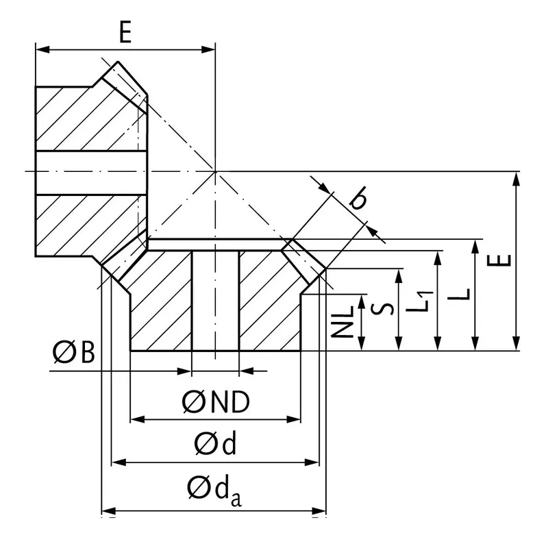 |
| Modulo | Numero di denti | dUN | d | ND | Paesi Bassi | L1 | L | S | b | BH7 | E | Coppia* | Peso |
| mm | mm | mm | mm | mm | mm | mm | mm | mm | mm | Ncm | g | ||
| 1 | 15 | 17,8 | 15 | 13 | 7,7 | 17,3 | 17,3 | 8,4 | 9,3 | 5 | 38 | 0,14 | 15 |
| 1 | 60 | 60,3 | 60 | 30 | 10,0 | 15 | 17,1 | 15,1 | 9,3 | 8 | 22 | 0,56 | 160 |
| 1,5 | 15 | 26,7 | 22,5 | 18 | 14,45 | 28 | 28,9 | 15,5 | 13,9 | 8 | 60 | 0,48 | 42 |
| 1,5 | 60 | 90,4 | 90 | 50 | 12,0 | 25 | 27,6 | 24,6 | 13,9 | 15 | 35 | 1,92 | 745 |
| 2 | 15 | 34,0 | 30 | 20 | 13,5 | 29 | 29,9 | 15,5 | 15 | 10 | 75 | 1,34 | 80 |
| 2 | 60 | 120,9 | 120 | 60 | 20,0 | 35 | 40,1 | 37,0 | 15 | 25 | 50 | 5,36 | 1600 |
| 2,5 | 15 | 42,5 | 37,5 | 30 | 16,1 | 35 | 36,8 | 17,6 | 20 | 10 | 92 | 2,5 | 190 |
| 2,5 | 60 | 151,2 | 150 | 80 | 18,0 | 33 | 37,8 | 33,8 | 20 | 25 | 50 | 10,0 | 2600 |
| 3 | 15 | 51,0 | 45 | 30 | 13,15 | 38 | 39,7 | 15,7 | 25 | 10 | 105 | 4,4 | 270 |
| 3 | 60 | 181,5 | 180 | 80 | 18,0 | 35 | 40,6 | 35,5 | 25 | 30 | 55 | 17,6 | 3800 |
| 4 | 15 | 68,0 | 60 | 40 | 12,5 | 43 | 44,8 | 16,0 | 30 | 20 | 135 | 8,9 | 520 |
| 4 | 60 | 242,0 | 240 | 90 | 20,0 | 41 | 50,1 | 44,0 | 30 | 30 | 70 | 35,6 | 8300 |
Advantages of Stainless Steel Bevel Gears
Elevata capacità di coppia
One of the key advantages of stainless steel bevel gears is their ability to handle high torque loads. The geometry and design of bevel gears allow for efficient transmission of power and torque between intersecting shafts.
Design compatto
Gli ingranaggi conici offrono una soluzione compatta per la trasmissione di potenza tra alberi non paralleli. Grazie alla geometria conica, gli ingranaggi conici possono cambiare efficacemente il senso di rotazione in uno spazio limitato.
Funzionamento fluido e silenzioso
Se progettati e realizzati correttamente, gli ingranaggi conici possono garantire un funzionamento fluido e silenzioso. I progressi nella geometria dei denti degli ingranaggi, come l'uso di ingranaggi conici a spirale e ipoidi, hanno migliorato significativamente la scorrevolezza e la capacità di riduzione del rumore degli ingranaggi conici. Il profilo curvo dei denti degli ingranaggi conici a spirale consente un innesto e un disinnesto graduali, con conseguente funzionamento più silenzioso rispetto agli ingranaggi conici dritti.
Versatility in Shaft Angles
Gli ingranaggi conici offrono flessibilità in termini di angoli di inclinazione dell'albero che possono supportare. Sebbene l'angolo di inclinazione dell'albero più comune per gli ingranaggi conici sia di 90 gradi, possono essere progettati per funzionare con angoli di inclinazione dell'albero diversi.
Disadvantages of Stainless Steel Bevel Gears
Higher Manufacturing Complexity
One of the main disadvantages of stainless steel bevel gears is their higher manufacturing complexity compared to other gear types, such as spur gears. The production of bevel gears requires specialized machinery and precise manufacturing processes to achieve the desired tooth geometry and surface finish. This complexity can result in increased manufacturing costs and longer lead times.
Sensitivity to Misalignment
Gli ingranaggi conici sono più sensibili al disallineamento rispetto ad altri tipi di ingranaggi. Il disallineamento può causare una distribuzione non uniforme del carico, un aumento delle sollecitazioni sui denti degli ingranaggi e guasti prematuri.
Limited Speed Capability
Gli ingranaggi conici presentano dei limiti in termini di velocità. Ad alte velocità, tendono a generare rumorosità e vibrazioni eccessive a causa dello scorrimento tra i denti. Ciò può comportare una riduzione dell'efficienza e un aumento dell'usura. Di conseguenza, gli ingranaggi conici sono tipicamente utilizzati in applicazioni con requisiti di velocità da moderati a bassi.
Higher Cost
La complessità produttiva e la precisione richieste per gli ingranaggi conici si traducono spesso in costi più elevati rispetto a tipologie di ingranaggi più semplici. La necessità di macchinari specializzati, manodopera qualificata e rigorosi controlli di qualità contribuiscono all'aumento del costo degli ingranaggi conici. Inoltre, la personalizzazione e i requisiti di progettazione specifici degli ingranaggi conici per applicazioni specifiche possono aumentarne ulteriormente il costo.
What Are Bevel Gears Used For
Power Transmission in Automobiles
Bevel gears find extensive use in the automotive industry, particularly in differential drives. In a differential, straight bevel gears are used to split the power from the driveshaft and transmit it to the wheels while allowing them to rotate at different speeds. This enables smooth cornering and improved traction control. Bevel gears are also used in various other automotive applications, such as transfer cases and steering systems.
Macchinari industriali
Bevel gears are commonly used in industrial machinery where power needs to be transmitted between intersecting shafts. They are found in a wide range of equipment, including gearboxes, speed reducers, and power transmission systems. Industrial applications that utilize bevel gears include mining machinery, construction equipment, printing presses, and textile machinery.
Aerospace and Aviation
The aerospace and aviation industries rely on stainless steel bevel gears for power transmission in various applications. Bevel gears are used in aircraft engines, rotor drive systems, and accessory gearboxes. They are designed to handle high loads and provide reliable performance in demanding operating conditions. The compact design and ability to transmit power between non-parallel shafts make bevel gears well-suited for aerospace applications where space is limited.
Marine Applications
Bevel gears are employed in marine applications for power transmission in propulsion systems, steering systems, and deck machinery. They are used in marine gearboxes, thrusters, and winches. The ability of bevel gears to handle high torque loads and withstand harsh marine environments makes them suitable for these applications. Marine bevel gears are often manufactured from corrosion-resistant materials to ensure durability and reliability.
 |  |
| Ingranaggi conici per differenziali automobilistici | Ingranaggi conici per macchinari industriali |
 |  |
| Ingranaggio conico per robotica | Ingranaggi conici per l'industria marina |
Stainless Steel Bevel Gear Measurement
Step 1: Gather Required Tools and Equipment
To accurately measure bevel gears, you will need the following tools:
- Vernier caliper or micrometer for measuring tooth thickness, depth, and pitch diameter
- Bevel protractor for measuring pitch and root angles
- Gear tooth vernier caliper for measuring tooth thickness at a specific depth
- Surface plate and height gauge for checking gear runout and mounting distance
Step 2: Measure Pitch Diameter
To measure pitch diameter:
- Place the bevel gear on a surface plate with the back face down.
- Position the height gauge perpendicular to the surface plate and align its measuring tip with the pitch line on a gear tooth flank.
- Zero the height gauge at this position.
- Rotate the gear 180 degrees and measure the height at the corresponding pitch line on the opposite tooth flank.
- The pitch diameter is calculated by adding the two height measurements.
Repeat this process on multiple teeth around the gear to ensure consistency and check for potential runout issues.
Step 3: Measure Tooth Thickness
To measure tooth thickness:
- Use a gear tooth vernier caliper positioned at the pitch line.
- Measure the thickness of a tooth at the pitch line, taking care not to damage the tooth profile.
- Repeat this measurement on several teeth around the gear, noting any variations.
Alternatively, a standard vernier caliper or micrometer can be used to measure the chordal thickness at the base of the tooth.
Step 4: Measure Pressure and Root Angles
To measure these angles:
- Place the bevel protractor on the pitch cone of the gear, aligning its edge with a tooth flank.
- Read the pressure angle directly from the protractor scale at the point of tangency with the tooth profile.
- Reposition the protractor to align with the root line of the tooth to measure the root angle.
Verify that the measured angles match the specified gear design parameters.
Step 5: Inspect Gear Runout
Gear runout refers to the variation in gear geometry as it rotates about its axis. To check runout:
- Mount the bevel gear on a mandrel or arbor supported by V-blocks on a surface plate.
- Position a dial indicator with its probe contacting the back face of the gear near the outer diameter.
- Slowly rotate the gear, noting the total indicator reading (TIR) on the dial.
- Compare the measured TIR to the specified tolerance for runout.
Repeat this process at the front face of the gear and at the pitch diameter to fully evaluate gear runout.
Step 6: Verify Mounting Distance
The mounting distance is the axial position of the bevel gear relative to its mating gear. To verify mounting distance:
- Place the bevel gear on a surface plate with its front face down.
- Use a height gauge to measure the distance from the surface plate to the back face of the gear at the specified mounting distance radius.
- Compare this measurement to the gear’s designed mounting distance.
Informazioni aggiuntive
| A cura di | Yjx |
|---|
Prodotti correlati
-
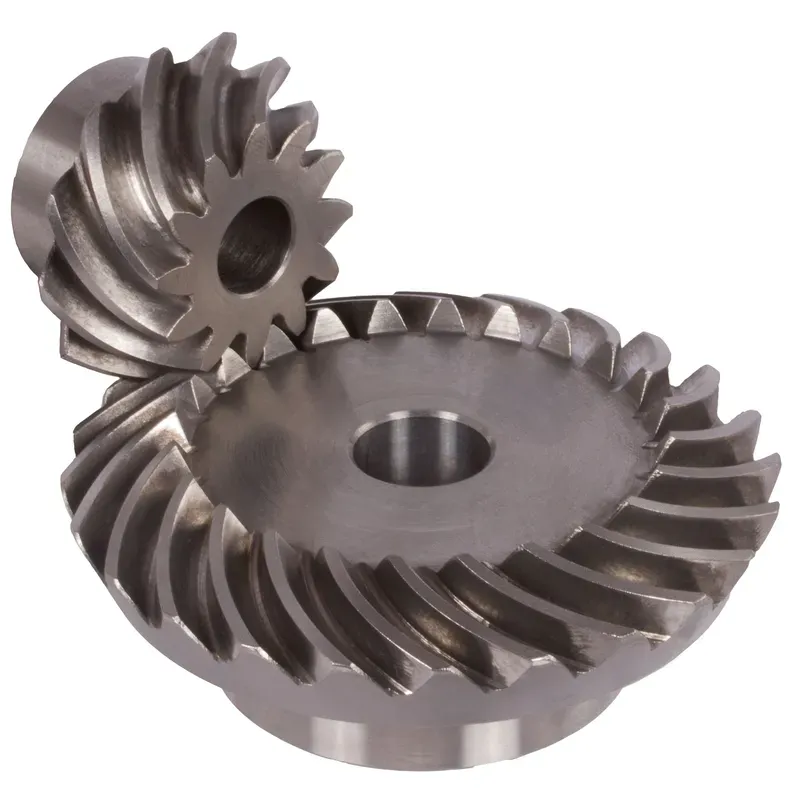
Steel Spiral Bevel Gears Ratio 1:1 Spiral Tooth System
-
Ingranaggi conici a mitra in acciaio, rapporto 1:1, sistema a denti dritti
-
Stainless Steel Bevel Gears Ratio 2:1 Straight-Tooth System
-
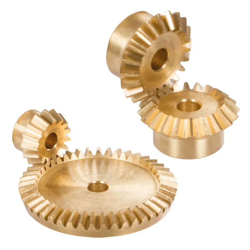
Brass Bevel Gears Ratio 1:1 – 4:1 Straight-Tooth System
-
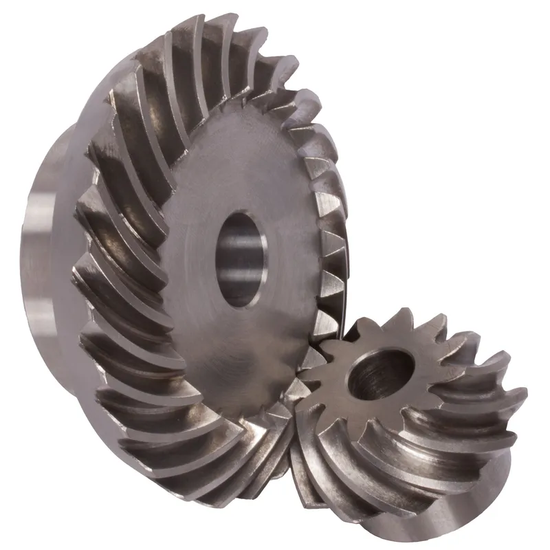
Ingranaggi conici a spirale in acciaio Rapporto 2,5:1 Sistema di denti a spirale


