In industries that rely on machinery, the transmission of power and motion is a fundamental requirement. Gears, specifically spiral bevel gears, play an indispensable role in making this transmission possible in a wide range of applications.
Spiral bevel gears are a specialized type of gear that allows for smooth and efficient transfer of power between intersecting shafts. Their unique geometry and design considerations enable them to handle high loads, high speeds, and demanding operating conditions.
What Is a Spiral Bevel Gear
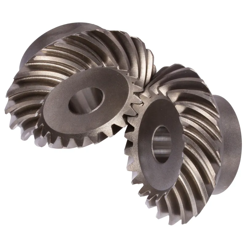
A spiral bevel gear is a specialized type of bevel gear featuring teeth that are curved and set at an angle to the axis of the gear. This unique geometry allows spiral bevel gears to transmit power between two intersecting shafts that are non-parallel and do not intersect at a right angle (90 degrees). The spiral angle of the gear teeth enables a gradual and smooth meshing action, resulting in quieter operation, higher load carrying capacity, and improved efficiency compared to straight bevel gears.
Spiral Angle and Direction of Rotation
The spiral angle is a critical parameter in the design of spiral bevel gears. It is defined as the angle between the tooth trace and an imaginary line perpendicular to the axis of the gear. The spiral angle determines the direction of the thrust load and influences the efficiency, noise level, and load-carrying capacity of the gear set.
Spiral bevel gears can be designed with either a right-hand or left-hand spiral angle. The hand of the spiral angle determines the direction of rotation of the gear set. A right-hand spiral angle means that the gear will rotate clockwise when viewed from the larger end of the gear, while a left-hand spiral angle will result in counterclockwise rotation.
How Spiral Bevel Gears Work
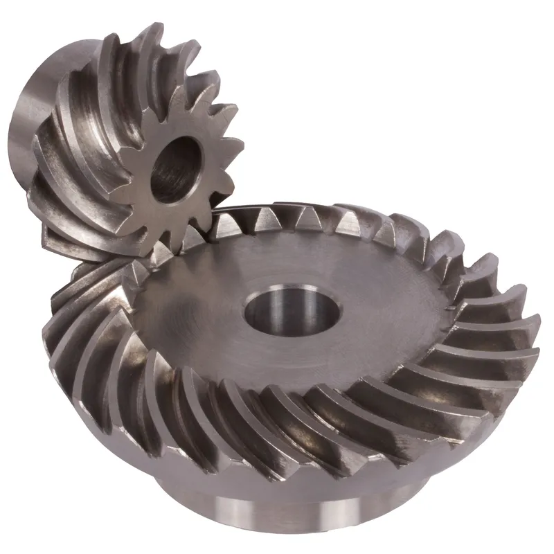
Spiral bevel gears operate by transmitting torque and rotational motion between two shafts that are not parallel and do not intersect at a right angle. The spiral teeth of the gears engage gradually, starting at one end of the tooth and progressing towards the other end as the gears rotate. This gradual engagement reduces the impact and noise associated with gear meshing, as the load is distributed over a larger contact area.
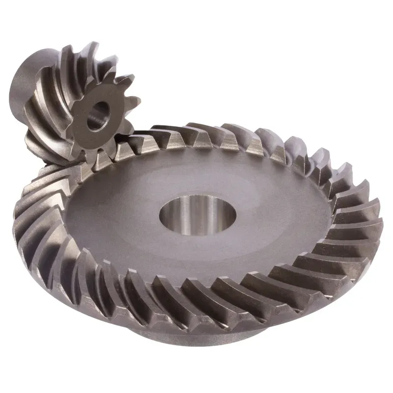
The driving gear, also known as the pinion, typically has fewer teeth than the driven gear, or ring gear. As the pinion rotates, it drives the ring gear, resulting in a change in both the speed and direction of rotation. The speed ratio between the two gears is determined by the number of teeth on each gear, while the direction of rotation is influenced by the hand of the spiral angle.
The Formulas Behind Gear Ratio, Speed, and Torque Calculations
To understand the performance characteristics of spiral bevel gears, it is essential to be familiar with the formulas used to calculate gear ratio, speed, and torque.
- Gear Ratio:
The gear ratio is the relationship between the number of teeth on the ring gear (NR) and the number of teeth on the pinion (NP). It is calculated using the following formula:
Gear Ratio = NR / NP
- Speed Ratio:
The speed ratio is the relationship between the rotational speed of the pinion (nP) and the rotational speed of the ring gear (nR). It is the reciprocal of the gear ratio and is calculated using the following formula:
Speed Ratio = nP / nR = NR / NP
- Torque Ratio:
The torque ratio is the relationship between the torque on the ring gear (TR) and the torque on the pinion (TP). It is equal to the gear ratio and is calculated using the following formula:
Torque Ratio = TR / TP = NR / NP
Differentiating from Other Bevel Gears
| Bevel Gear Type | Tooth Shape | Noise Level | Load Capacity | Efficiency |
|---|---|---|---|---|
| Straight Bevel | Straight | High | Low | Low |
| Spiral Bevel | Spiral | Low | High | High |
| Zerol Bevel | Curved | Moderate | Moderate | Moderate |
| Hypoid Bevel | Spiral | Low | High | High |
Advantages of Spiral Bevel Gears
Smooth and Quiet Operation
The spiral tooth geometry of spiral bevel gears results in gradual engagement and disengagement of the gear teeth, reducing the impact and vibration associated with gear meshing.
High Load Carrying Capacity
Spiral bevel gears have a higher load-carrying capacity compared to straight bevel gears due to their spiral tooth geometry. The angled teeth distribute the load over a larger contact area, reducing the stress on individual teeth and allowing spiral bevel gears to transmit higher torques and handle heavier loads.
Increased Efficiency
The gradual engagement and disengagement of the spiral teeth in bevel gears result in reduced sliding friction between the mating teeth.
Versatility in Shaft Arrangements
Spiral bevel gears offer flexibility in shaft arrangements, as they can transmit power between shafts that are non-parallel and do not intersect at a right angle.
Design Considerations
Material Selection
The selection of materials for spiral bevel gears depends on the specific application requirements, such as load, speed, operating environment, and expected service life. Common materials include:
- Steel: Various grades of steel, such as carbon steel, alloy steel, and case-hardened steel, are widely used for their strength, durability, and wear resistance.
- Cast Iron: Cast iron is a cost-effective option for lower-performance applications and is known for its good machinability and damping properties.
- Brass and Bronze: These materials are used for applications requiring low friction and good wear resistance, such as in worm gears.
- Plastics: Plastic gears, such as those made from nylon or acetal, are lightweight, corrosion-resistant, and suitable for low-load applications.
Tooth Geometry
The tooth geometry of spiral bevel gears is defined by several parameters, including the spiral angle, pressure angle, face width, and tooth thickness. These parameters influence the gear’s performance, load capacity, and efficiency. The spiral angle is a critical factor, as it determines the direction of the thrust load and affects the gear’s noise level and smoothness of operation.
Manufacturing Processes
Spiral bevel gears are typically manufactured using specialized machining processes, such as:
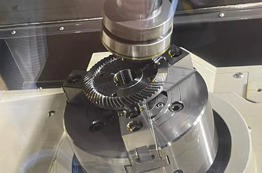
- Face Milling: A multi-tooth cutter is used to generate the tooth profile by rotating and simultaneously feeding the cutter across the face of the gear blank.
- Face Hobbing: A hob, which is a cutting tool with helical threads, is used to generate the tooth profile by rotating and feeding the hob across the face of the gear blank.
- Forging: Forged spiral bevel gears are formed by hot- or cold-pressing a gear blank in a die, resulting in improved grain flow and enhanced mechanical properties.
- 3D Printing: Additive manufacturing techniques, such as metal 3D printing, are increasingly being used for prototyping and low-volume production of spiral bevel gears.
Mounting and Installation
Proper mounting and installation of spiral bevel gears are crucial for ensuring optimal performance and long service life. Key considerations include:
- Shaft Alignment: Accurate alignment of the gear shafts is essential to prevent uneven loading, excessive wear, and premature failure.
- Bearing Selection: Appropriate bearing selection and placement help to support the gear shafts, reduce friction, and maintain proper gear mesh.
- Lubrication: Adequate lubrication is necessary to reduce friction, dissipate heat, and prevent wear between the mating gear teeth.
- Backlash Adjustment: Backlash, or the clearance between mating gear teeth, must be properly adjusted to ensure smooth operation and prevent excessive wear or noise.
Backlash
Backlash is the amount of clearance or play between the mating teeth of spiral bevel gears. It is necessary to accommodate manufacturing tolerances, thermal expansion, and elastic deformation under load. However, excessive backlash can lead to noise, vibration, and reduced positioning accuracy. Insufficient backlash, on the other hand, can cause binding, increased friction, and accelerated wear.
To achieve optimal performance, backlash must be carefully controlled during the design and manufacturing process. This can be done through precise machining, selective assembly, or the use of backlash-reducing design features such as spring-loaded split gears or adjustable mounting systems.
Lubrication
Proper lubrication is essential for the efficient and reliable operation of spiral bevel gears. Lubrication serves several purposes:
- Reducing friction and wear between mating gear teeth.
- Dissipating heat generated during operation.
- Protecting against corrosion and contamination.
- Flushing away wear debris and contaminants.
The choice of lubricant depends on factors such as the operating temperature, speed, load, and environment. Common lubricants for spiral bevel gears include:
- Gear Oils: These are specially formulated oils with additives to improve their load-carrying capacity, wear resistance, and oxidation stability.
- Greases: Greases are used in applications where oil lubrication is not practical, such as in sealed-for-life gear boxes.
- Solid Lubricants: In extreme temperature or vacuum environments, solid lubricants like molybdenum disulfide or graphite may be used.

Applications of Spiral Bevel Gears
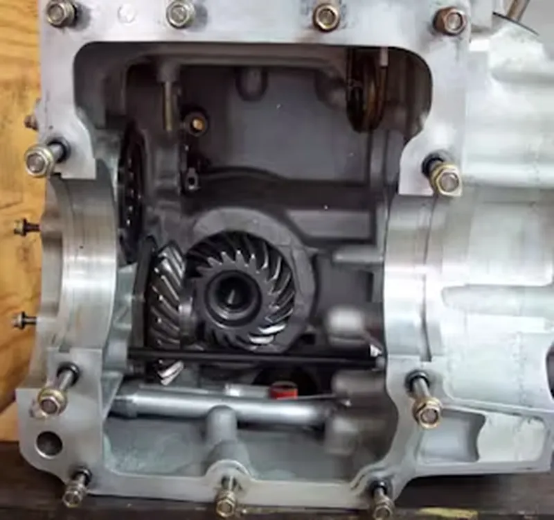
Automotive Drivetrains
Spiral bevel gears are extensively used in automotive drivetrains, particularly in the differential assembly of rear-wheel-drive vehicles. The differential allows the drive wheels to rotate at different speeds when turning, while still providing power to both wheels. Spiral bevel gears are preferred in this application due to their smooth operation, low noise, and high load-carrying capacity.
Aerospace Systems
In aerospace applications, spiral bevel gears are used in a variety of systems, including flight control actuators, landing gear, and power transmission units. These gears are favored for their high efficiency, reliability, and ability to transmit power between non-parallel shafts in compact spaces.
Industrial Machinery
Spiral bevel gears find wide application in industrial machinery, such as:
- Gearboxes and speed reducers
- Conveyor systems
- Pumps and compressors
- Machine tools and robotics
Marine Propulsion Systems
In marine propulsion systems, spiral bevel gears are used in the transmission of power from the engine to the propeller shaft. These gears are designed to withstand the high torques and shock loads encountered in marine environments while providing smooth and quiet operation.

Common Issues with Spiral Bevel Gears
Despite their many advantages, spiral bevel gears can experience several common issues:
- Tooth Wear: Excessive wear of the gear teeth can occur due to factors such as inadequate lubrication, misalignment, overloading, or contamination. Regular inspection and maintenance can help prevent premature tooth wear.
- Pitting: Surface fatigue can cause small pits to form on the gear teeth, leading to increased noise, vibration, and eventual gear failure. Proper lubrication and filtration can help mitigate pitting.
- Scoring: Scoring is a severe form of surface damage caused by inadequate lubrication or excessive loads, resulting in deep scratches on the gear teeth. Proper lubrication and load management are essential to prevent scoring.
- Misalignment: Misalignment of the gear shafts can cause uneven load distribution, leading to increased wear, noise, and vibration. Accurate alignment during installation and regular checks can help prevent misalignment issues.
- Backlash Variation: Changes in backlash due to wear, thermal expansion, or improper adjustment can affect gear performance and cause positioning errors. Regular backlash checks and adjustment can help maintain optimal gear operation.