Bevel gears are a fundamental component in many mechanical systems, enabling the efficient transmission of power between intersecting shafts. These gears feature unique geometry, with teeth cut on a conical surface, allowing them to operate smoothly and reliably even when the shafts are not parallel.
What is a Bevel Gear
A bevel gear is a type of gear that features conically-shaped teeth, allowing it to transmit power between intersecting shafts at various angles, most commonly 90 degrees. Unlike spur gears, which have teeth parallel to the shaft axis, bevel gears possess teeth that are formed on a cone, enabling them to change the direction of rotation and shaft angle simultaneously.
The geometry of bevel gears is more complex than other gear types due to their three-dimensional nature. The teeth on a bevel gear are cut on a cone-shaped blank, with the pitch surface forming a cone at the proper shaft angle. This unique design allows bevel gears to handle both radial and thrust loads effectively.
How Bevel Gears Work
Bevel gears are designed to transmit power and motion between intersecting shafts, typically at a 90-degree angle. The teeth of bevel gears are formed on conical surfaces, allowing them to mesh and transfer torque efficiently.
The working principle of bevel gears involves the meshing of teeth on two cone-shaped gear wheels. The cone angles of these gears are designed such that the pitch surfaces of the teeth roll on each other without slipping. This rolling action enables the smooth transmission of power and rotation between the intersecting shafts.
In a bevel gear system, the pinion is the smaller gear that drives the larger gear, known as the crown gear or ring gear. The pinion is typically mounted on the input shaft, while the crown gear is attached to the output shaft. As the pinion rotates, its teeth engage with the teeth of the crown gear, causing it to rotate as well.
The gear ratio of bevel gears is determined by the number of teeth on the pinion and the crown gear. A higher gear ratio indicates that the crown gear has more teeth than the pinion, resulting in a speed reduction and torque multiplication. Conversely, a lower gear ratio means that the pinion has more teeth than the crown gear, leading to a speed increase and torque reduction.
Basic Characteristics of Bevel Gears
| Characteristic | Description | Formula (where applicable) |
|---|---|---|
| Pitch Diameter (D) | The diameter of the pitch circle measured at the large end of the gear | D = N/P (N: number of teeth, P: diametral pitch) |
| Pitch Angle (γ) | The angle between the gear’s axis and the pitch cone element | tan γ = (number of teeth on gear)/(number of teeth on mating gear) |
| Face Width (F) | The length of the teeth measured along the pitch cone element | Generally ≤ 1/3 of the cone distance |
| Addendum (a) | The radial distance from the pitch circle to the top of the tooth | a = 1/P (for standard gears) |
| Dedendum (b) | The radial distance from the pitch circle to the root of the tooth | b = 1.157/P (for standard gears) |
| Whole Depth (ht) | Total depth of the tooth space | ht = a + b |
| Cone Distance (R) | The length of the pitch cone element from the apex to the outer edge | R = √(D²/4 + R₁²) where R₁ is mounting distance |
| Circular Pitch (p) | The distance between corresponding points on adjacent teeth measured along the pitch circle | p = π/P |
| Module (m) | Metric alternative to diametral pitch | m = D/N = 25.4/P |
| Pressure Angle (φ) | The angle between the tooth profile and a radial line at the pitch circle | Typically 20° or 14.5° |
| Back Cone Distance | The length of the pitch cone element to the back cone | Varies based on gear geometry |
| Root Angle | The angle between the root cone element and the gear axis | Slightly less than pitch angle |
| Face Angle | The angle between the face cone element and the gear axis | Slightly more than pitch angle |
Types of Bevel Gears
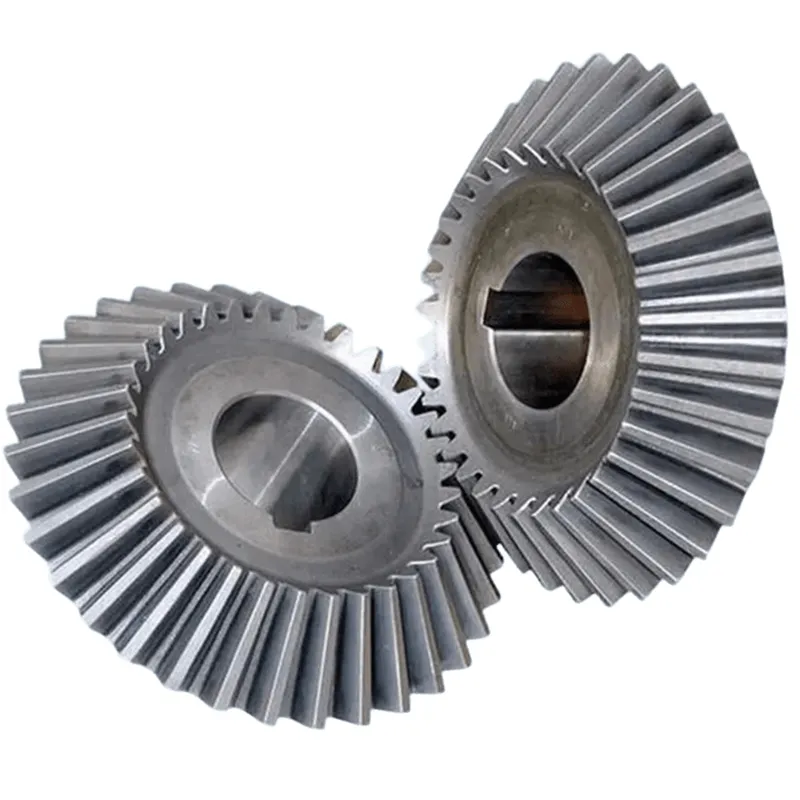
Straight Bevel Gears
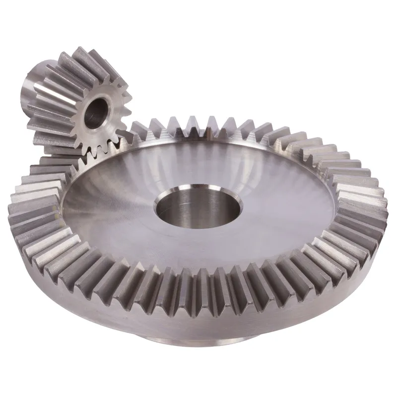
Straight bevel gears are the simplest type of bevel gears, featuring straight teeth that are parallel to the generatrix of the pitch cone. They are used in applications where high speeds and low to medium loads are present. However, straight bevel gears may generate more noise compared to other types of bevel gears due to the sudden engagement of the teeth.
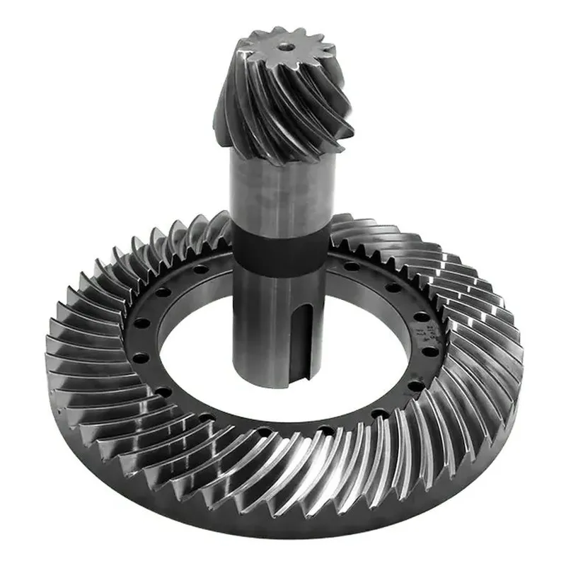
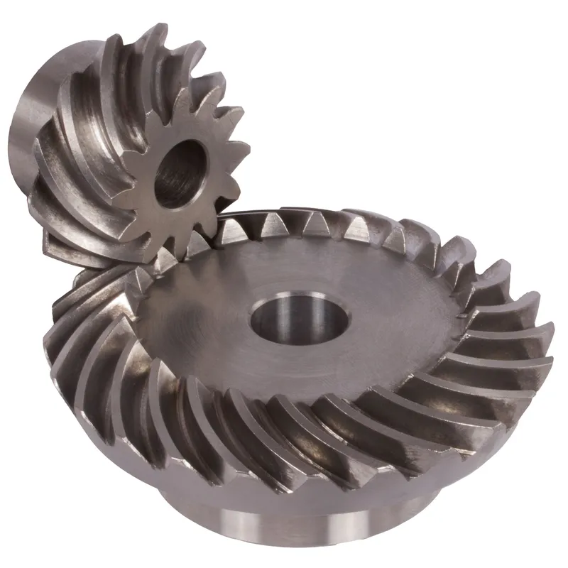
Spiral Bevel Gears
Spiral bevel gears have curved teeth that are oblique to the generatrix of the pitch cone. The spiral angle of the teeth provides a gradual and smooth engagement, resulting in quieter operation and higher load capacity compared to straight bevel gears. Spiral bevel gears are commonly used in automotive differentials and industrial applications that require high speeds and heavy loads.
Hypoid Bevel Gears
Hypoid bevel gears are similar to spiral bevel gears but with a notable difference: the pitch cones of the gears do not intersect. Instead, the axes of the gears are offset, allowing for larger pinion diameters and improved tooth contact. This offset configuration provides several advantages, such as higher torque capacity, reduced noise, and more compact designs. Hypoid gears are frequently used in automotive rear axles and industrial gearboxes.
Zerol Bevel Gears
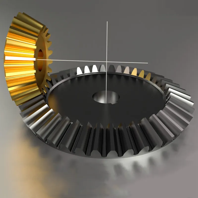
Zerol bevel gears are a special case of spiral bevel gears, where the spiral angle is zero. This means that the teeth are parallel to the axis of rotation, similar to straight bevel gears. However, unlike straight bevel gears, Zerol bevel gears have a curved tooth profile that allows for smooth and gradual engagement. Zerol bevel gears offer a balance between the benefits of straight and spiral bevel gears, providing improved load capacity and quieter operation compared to straight bevel gears.
Miter Gears
Miter gears are a specific type of bevel gear where the number of teeth on both gears is equal, and the shaft angle is 90°. This configuration results in a 1:1 gear ratio, making miter gears ideal for applications that require a change in the direction of rotation without altering the speed or torque. Miter gears can have straight, spiral, or Zerol teeth.
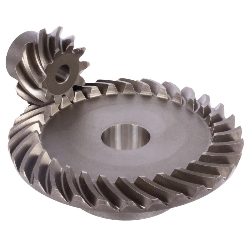 | 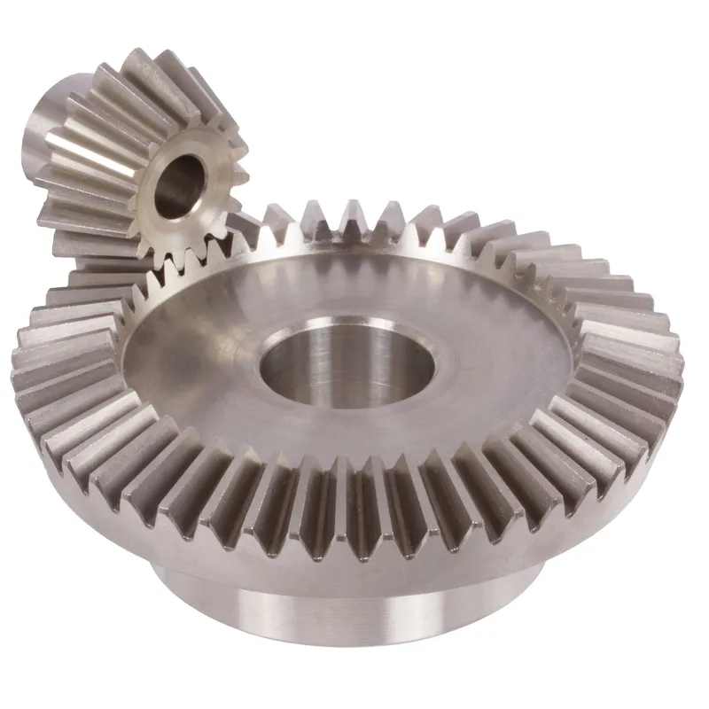 |
| Spiral Bevel Gears | Straight Bevel Gears |
 |  |
| Hypoid Bevel Gears | Zerol Bevel Gears |
Bevel Gear Efficiency Reference Table
General Efficiency Ranges
| Gear Type | Typical Efficiency Range | Optimal Operating Conditions |
|---|---|---|
| Straight Bevel | 96-98% | Low to medium speeds, properly aligned |
| Spiral Bevel | 95-97% | Medium to high speeds, well-lubricated |
| Zerol Bevel | 94-96% | Medium speeds, moderate loads |
| Hypoid Bevel | 90-95% | High speeds, heavy loads |
Efficiency Factors by Operating Conditions
| Operating Condition | Impact on Efficiency | Typical Efficiency Loss |
|---|---|---|
| Low Speed (<1000 RPM) | Minimal losses | 0.5-1% |
| High Speed (>3000 RPM) | Increased losses | 2-5% |
| Poor Lubrication | Significant losses | 5-10% |
| Misalignment | Major losses | 3-8% |
| Heavy Loading | Moderate losses | 2-4% |
Lubrication Impact on Efficiency
| Lubrication Type | Efficiency Impact | Recommended Applications |
|---|---|---|
| Oil Bath | Highest efficiency | High-speed, heavy loads |
| Grease | Good efficiency | Low to medium speeds |
| Splash | Moderate efficiency | Medium speeds |
| Minimal | Poor efficiency | Light loads only |
Temperature Effects
| Operating Temperature | Efficiency Impact | Maintenance Requirements |
|---|---|---|
| <20°C | Reduced efficiency | More frequent lubrication |
| 20-40°C | Optimal efficiency | Standard maintenance |
| 40-60°C | Slightly reduced | Increased monitoring |
| >60°C | Significantly reduced | Special lubrication needed |
Material Combination Efficiency
| Pinion/Gear Material | Efficiency Range | Wear Characteristics |
|---|---|---|
| Steel/Steel | 95-98% | Excellent durability |
| Steel/Bronze | 93-96% | Good wear resistance |
| Steel/Plastic | 90-94% | Lower noise, shorter life |
| Hardened/Unhardened Steel | 92-95% | Moderate wear resistance |
Size Impact on Efficiency
| Gear Module Range | Typical Efficiency | Best Applications |
|---|---|---|
| <3 mm | 92-95% | Precision instruments |
| 3-6 mm | 94-97% | General machinery |
| 6-12 mm | 95-98% | Heavy equipment |
| >12 mm | 93-96% | Industrial drives |
Advantages of Bevel Gears
High Torque Capacity
One of the key advantages of bevel gears is their ability to handle high torque loads. The geometry and design of bevel gears allow for efficient transmission of power and torque between intersecting shafts.
Compact Design
Bevel gears offer a compact solution for power transmission between non-parallel shafts. By utilizing a conical geometry, bevel gears can effectively change the direction of rotation within a limited space.
Smooth and Quiet Operation
When properly designed and manufactured, bevel gears can provide smooth and quiet operation. Advancements in gear tooth geometry, such as the use of spiral bevel gears and hypoid gears, have significantly improved the smoothness and noise reduction capabilities of bevel gears. The curved teeth profile of spiral bevel gears allows for gradual engagement and disengagement, resulting in quieter operation compared to straight bevel gears.
Versatility in Shaft Angles
Bevel gears offer flexibility in terms of the shaft angles they can accommodate. While the most common shaft angle for bevel gears is 90 degrees, they can be designed to work with various shaft angles.
Disadvantages of Bevel Gears
Higher Manufacturing Complexity
One of the main disadvantages of bevel gears is their higher manufacturing complexity compared to other gear types, such as spur gears. The production of bevel gears requires specialized machinery and precise manufacturing processes to achieve the desired tooth geometry and surface finish. This complexity can result in increased manufacturing costs and longer lead times.
Sensitivity to Misalignment
Bevel gears are more sensitive to misalignment compared to other gear types. Misalignment can lead to uneven load distribution, increased stress on gear teeth, and premature failure.
Limited Speed Capability
Bevel gears have limitations in terms of their speed capability. At high speeds, bevel gears are prone to generating excessive noise and vibration due to the sliding action between the gear teeth. This can lead to reduced efficiency and increased wear. As a result, bevel gears are typically used in applications with moderate to low speed requirements.
Higher Cost
The manufacturing complexity and precision required for bevel gears often translate to higher costs compared to simpler gear types. The need for specialized machinery, skilled labor, and stringent quality control measures contributes to the increased cost of bevel gears. Additionally, the customization and specific design requirements of bevel gears for particular applications can further increase their cost.
What Is a Bevel Gear Used For
Power Transmission in Automobiles
Bevel gears find extensive use in the automotive industry, particularly in differential drives. In a differential, bevel gears are used to split the power from the driveshaft and transmit it to the wheels while allowing them to rotate at different speeds. This enables smooth cornering and improved traction control. Bevel gears are also used in various other automotive applications, such as transfer cases and steering systems.
Industrial Machinery
Bevel gears are commonly used in industrial machinery where power needs to be transmitted between intersecting shafts. They are found in a wide range of equipment, including gearboxes, speed reducers, and power transmission systems. Industrial applications that utilize bevel gears include mining machinery, construction equipment, printing presses, and textile machinery.
Aerospace and Aviation
The aerospace and aviation industries rely on bevel gears for power transmission in various applications. Bevel gears are used in aircraft engines, rotor drive systems, and accessory gearboxes. They are designed to handle high loads and provide reliable performance in demanding operating conditions. The compact design and ability to transmit power between non-parallel shafts make bevel gears well-suited for aerospace applications where space is limited.
Marine Applications
Bevel gears are employed in marine applications for power transmission in propulsion systems, steering systems, and deck machinery. They are used in marine gearboxes, thrusters, and winches. The ability of bevel gears to handle high torque loads and withstand harsh marine environments makes them suitable for these applications. Marine bevel gears are often manufactured from corrosion-resistant materials to ensure durability and reliability.
 |  |
 |  |
FAQs
Do bevel gears increase speed?
No, bevel gears do not inherently increase speed. They are used to transfer power between intersecting shafts, typically at 90-degree angles. The gear ratio determines whether the output speed is increased or decreased relative to the input speed. Bevel gears with a higher number of teeth on the driven gear will result in a speed reduction.
Do bevel gears increase torque?
Yes, bevel gears can increase torque depending on the gear ratio. When the driven gear has more teeth than the driving gear, the output torque will be higher than the input torque. This is because the gear ratio multiplies the input torque, allowing bevel gears to increase torque at the expense of speed.
Are bevel gears expensive?
Generally, bevel gears are more expensive than spur gears due to their complex geometry and the need for specialized manufacturing equipment. However, the cost is justified in applications where power transmission between intersecting shafts is necessary.