Inaccurate bevel gear measurements lead to poor performance, premature failures, and costly rework in machinery applications. Imprecise dimensions and deviations from gear standards result in noisy operation, reduced power transmission efficiency, and alignment issues that can bring production lines to a halt.
Key Dimensions & Angles of Bevel Gears
Bevel gears are complex mechanical components characterized by a range of critical dimensions and angles.
A. Detailed Examination of Basic Dimensions
Several key dimensions define the overall geometry and size of a bevel gear:
- Pitch Diameter: This diameter is measured at the heel end of the bevel gear teeth. It represents the effective size of the gear and is a fundamental parameter for gear calculations and design.
- Pitch Cone Angle: The pitch cone angle describes the angle formed by the pitch cone relative to the gear axis. It defines the orientation of the gear teeth and determines how the gear meshes with its mating pinion.
- Addendum & Dedendum: The addendum is the height of the gear tooth above the pitch cone, while the dedendum is the depth below it. Together, they define the total tooth depth. The addendum and dedendum are typically specified in proportion to the gear module.
- Face Width: Face width refers to the size of the gear tooth measured along the pitch cone generatrix from the heel to the toe. It affects gear tooth strength and load capacity. Wider face widths generally allow greater torque transmission.
- Cone Distance: The cone distance represents the length from the apex of the pitch cone to the mid-face of the bevel gear. It is a key dimension for positioning the gear relative to its mating pinion during assembly.
- Vertex Distance: Vertex distance measures the offset from the gear axis to the pitch cone apex. It helps locate the theoretical point of mesh between gears.
B. Essential Bevel Gear Angles
In addition to linear dimensions, several angles are critical in defining a bevel gear’s geometry:
- Face Angle: The angle between the face cone generatrix and the gear axis. It determines the angle of the outer ends of the gear teeth relative to the rotational axis.
- Edge Angle: Measured between the outer cone generatrix and gear axis, the edge angle defines the slope of the inner ends of the teeth nearest the apex.
- Addendum Angle: This is the angular equivalent of the addendum, defining the tooth height in angular terms from the face angle to the outside edge.
- Dedendum Angle: Correspondingly, the dedendum angle measures the angular tooth depth from the pitch line down to the tooth root.
C. Backlash
Backlash refers to the clearance or play between the teeth of two meshing gears. Some backlash is necessary to accommodate lubrication, manufacturing tolerances, and thermal expansion. However, excessive backlash can cause noise, vibration, and imprecise positioning. Backlash is typically measured at the tightest point of mesh using dedicated tools or by assessing the angular play with the gears held fixed.
D. Module
The module of a gear is a standardized unit that indicates tooth size. It is defined as the ratio of the pitch diameter to the number of teeth. In bevel gears, the module is typically specified at the heel end for manufacturing purposes. Larger module numbers correspond to bigger, coarser teeth, while finer pitch gears have smaller modules.
Measuring Bevel Gears Step by Step
Step 1: Gather Required Tools and Equipment
To accurately measure bevel gears, you will need the following tools:
- Vernier caliper or micrometer for measuring tooth thickness, depth, and pitch diameter
- Bevel protractor for measuring pitch and root angles
- Gear tooth vernier caliper for measuring tooth thickness at a specific depth
- Surface plate and height gauge for checking gear runout and mounting distance
Step 2: Measure Pitch Diameter
To measure pitch diameter:
- Place the bevel gear on a surface plate with the back face down.
- Position the height gauge perpendicular to the surface plate and align its measuring tip with the pitch line on a gear tooth flank.
- Zero the height gauge at this position.
- Rotate the gear 180 degrees and measure the height at the corresponding pitch line on the opposite tooth flank.
- The pitch diameter is calculated by adding the two height measurements.
Repeat this process on multiple teeth around the gear to ensure consistency and check for potential runout issues.
Step 3: Measure Tooth Thickness
To measure tooth thickness:
- Use a gear tooth vernier caliper positioned at the pitch line.
- Measure the thickness of a tooth at the pitch line, taking care not to damage the tooth profile.
- Repeat this measurement on several teeth around the gear, noting any variations.
Alternatively, a standard vernier caliper or micrometer can be used to measure the chordal thickness at the base of the tooth.
Step 4: Measure Pressure and Root Angles
To measure these angles:
- Place the bevel protractor on the pitch cone of the gear, aligning its edge with a tooth flank.
- Read the pressure angle directly from the protractor scale at the point of tangency with the tooth profile.
- Reposition the protractor to align with the root line of the tooth to measure the root angle.
Verify that the measured angles match the specified gear design parameters.
Step 5: Inspect Gear Runout
Gear runout refers to the variation in gear geometry as it rotates about its axis. To check runout:
- Mount the bevel gear on a mandrel or arbor supported by V-blocks on a surface plate.
- Position a dial indicator with its probe contacting the back face of the gear near the outer diameter.
- Slowly rotate the gear, noting the total indicator reading (TIR) on the dial.
- Compare the measured TIR to the specified tolerance for runout.
Repeat this process at the front face of the gear and at the pitch diameter to fully evaluate gear runout.
Step 6: Verify Mounting Distance
The mounting distance is the axial position of the bevel gear relative to its mating gear. To verify mounting distance:
- Place the bevel gear on a surface plate with its front face down.
- Use a height gauge to measure the distance from the surface plate to the back face of the gear at the specified mounting distance radius.
- Compare this measurement to the gear’s designed mounting distance.

Specific Considerations for Different Bevel Gear Types
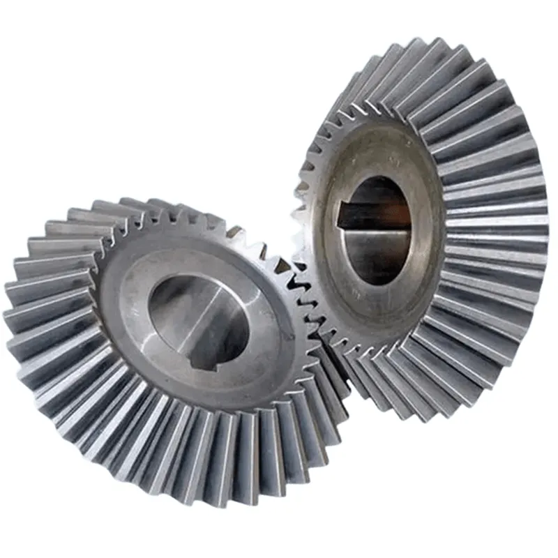
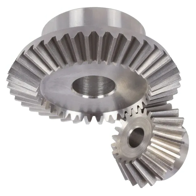
A. Straight Bevel Gears
Straight bevel gears feature teeth that are straight and conical. When measuring straight bevel gears, pay close attention to the following parameters:
- Pitch diameter: Measure the pitch diameter at the back cone distance. This is where the gear meshes with its mating pinion. Use a vernier caliper or micrometer for accurate measurements.
- Tooth thickness: Check the tooth thickness at the normal section. This is measured at the standard pitch circle. A gear tooth vernier is the preferred tool for this measurement.
- Back cone distance: This is the distance from the cone center to the back face of the gear. It’s a critical dimension that affects gear alignment. Measure it using a depth micrometer or a coordinate measuring machine (CMM).
- Face angle: The angle formed by the pitch cone with the back face of the gear is the face angle. This can be measured with a bevel protractor or on a CMM. Verify that it matches the specified design angle.
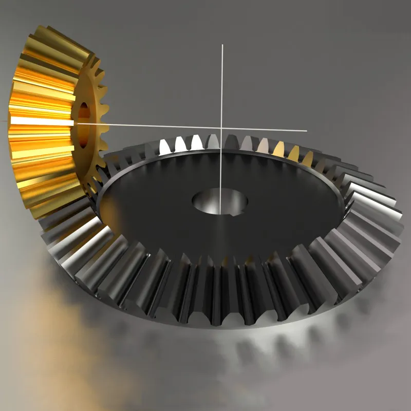
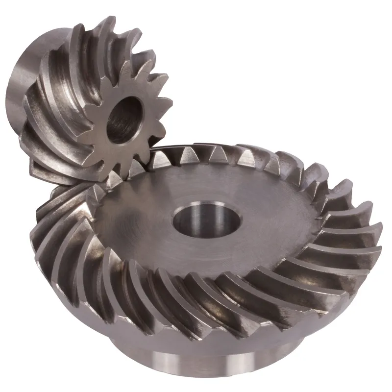
B. Spiral Bevel Gears
Spiral bevel gears have curved teeth that are positioned along diagonal lines across the surface of the cone. Key dimensions to check for spiral bevel gears include:
- Mean spiral angle: This is the angle between the tooth trace and an element of the pitch cone that passes through the middle of the tooth trace. It’s measured at the mean cone distance. Use a spiral bevel gear testing machine equipped with a dividing head for reliable measurements.
- Pressure angle: The pressure angle in a spiral bevel gear is measured at the mean point. It’s defined as the angle between a line normal to the tooth surface and a plane tangent to the pitch surface. Special tooling on a gear measuring machine is needed to accurately assess pressure angle.
- Pitch apex to crown: This is the distance in the axial plane between the pitch apex and the crown gear. The crown gear is the larger of the two mating spiral bevel gears. A direct measurement can be made using a depth micrometer.
C. Hypoid and Zerol Bevel Gears
Hypoid and Zerol bevel gears are special types of spiral bevel gears. Hypoid gears have an offset between the axes of the pinion and gear, while Zerol gears have zero offset. When measuring these gear types, focus on:
- Pitch apex to crown: Similar to spiral bevel gears, this dimension is critical for proper assembly and operation. Use a depth gauge to measure the distance from the heel end of the tooth to the pitch apex.
- Offset: For hypoid gears, the pinion axis is offset above or below the gear axis. This offset affects tooth contact and must be carefully controlled. It can be measured with a hypoid gear testing machine that simulates the operating positions of the gear and pinion.
- Spiral angle: Both hypoid and Zerol gears have spirally curved teeth. The spiral angle is defined at the mean point for these gear types. As with spiral bevel gears, use a spiral bevel gear tester with a dividing head to measure this parameter.