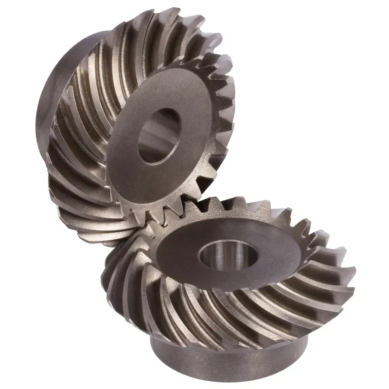
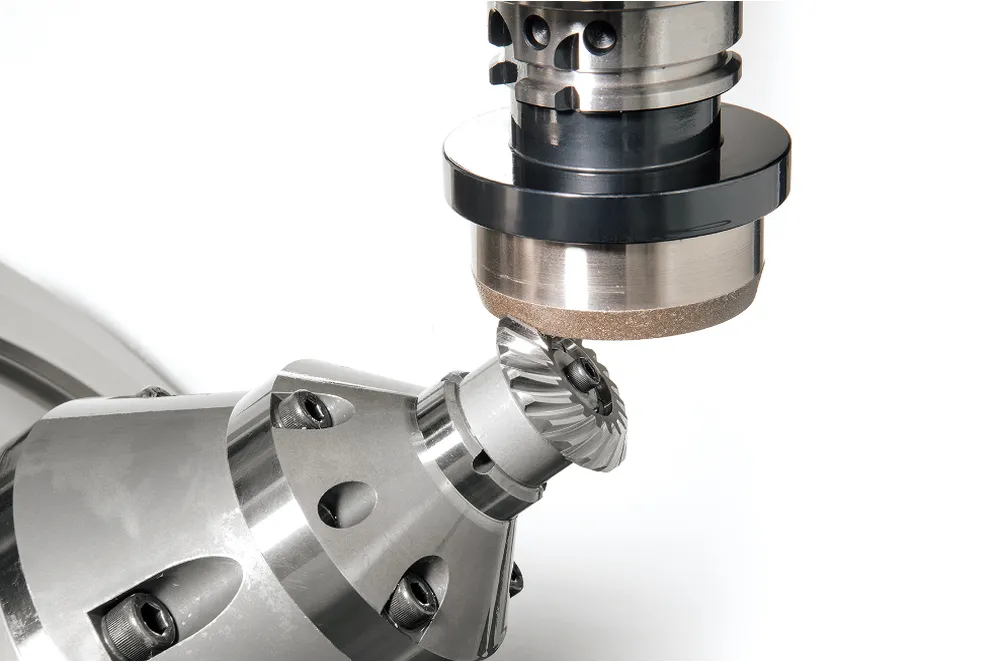
Steel Spiral Bevel Gears Ratio 1:1 Spiral Tooth System
Steel spiral bevel gears with a 1:1 ratio and spiral tooth system are conical gears designed to transmit power between intersecting shafts, typically at a 90-degree angle, with equal rotational speeds for both gears. The spiral tooth design features curved, oblique teeth set at a helix angle (often around 35°), ensuring gradual engagement, smoother operation, and higher load capacity compared to straight bevel gears.
Steel spiral bevel gears with a 1:1 ratio and spiral tooth system are conical gears designed to transmit power between intersecting shafts, typically at a 90-degree angle, with equal rotational speeds for both gears. The spiral tooth design features curved, oblique teeth set at a helix angle (often around 35°), ensuring gradual engagement, smoother operation, and higher load capacity compared to straight bevel gears. This reduces noise, vibration, and impact stress, making them ideal for high-speed, heavy-duty applications like automotive differentials, robotics, and industrial machinery.
Made from carbon or alloy steels, these spiral bevel gears are heat-treated for durability and precision, with a 1:1 ratio indicating identical tooth counts for the pinion and gear, often referred to as miter gears. Their efficiency ranges from 96-98%, but they generate axial thrust, requiring robust bearings.
Steel Spiral Bevel Gear Ratio 1:1
| 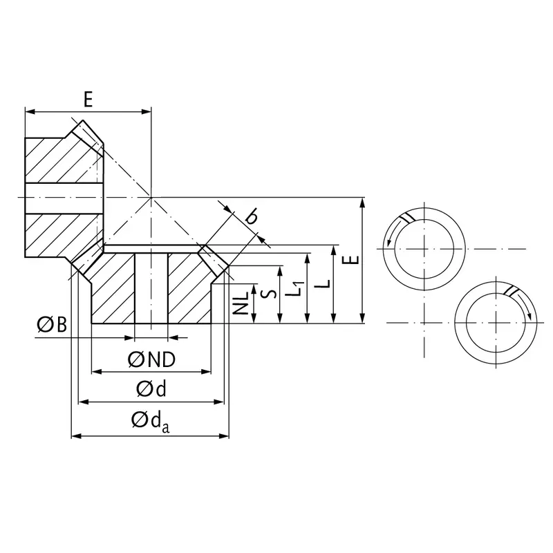 |
| Module | Number of teeth | da | d | ND | NL | L1 | L | S1) | b | BH7 | E | Torque* | Weight |
| mm | mm | mm | mm | mm | mm | mm | mm | mm | mm | Ncm | g | ||
| 0,6 | 16 | 15,8 | 15,5 | 10 | 4,5 | 9 | 10,0 | 7,7 | 3,3 | 5 | 15 | 0,64 | 12 |
| 0,6 | 20 | 16,9 | 16,5 | 12 | 6,5 | 11 | 12,0 | 9,2 | 4 | 5 | 17 | 1,27 | 19 |
| 0,6 | 25 | 23,3 | 22,5 | 19 | 7,2 | 12 | 13,4 | 9,2 | 6 | 6 | 20 | 2,1 | 50 |
| 0,6 | 30 | 27,8 | 27 | 22 | 7 | 13 | 14,9 | 9,9 | 7 | 8 | 23 | 3,0 | 75 |
| 0,6 | 35 | 32,3 | 31,5 | 25 | 7,2 | 15 | 16,3 | 10,6 | 8 | 8 | 26 | 3,5 | 116 |
| 1 | 16 | 25,4 | 24 | 17 | 7,5 | 13,5 | 15,95 | 11,7 | 6 | 6 | 23 | 2,5 | 55 |
| 1 | 20 | 31,4 | 30 | 25 | 8,4 | 15 | 17,3 | 11,7 | 8 | 8 | 26 | 6,3 | 112 |
| 1 | 25 | 38,9 | 37,5 | 25 | 8 | 16 | 19,0 | 11,9 | 10 | 10 | 30 | 10,0 | 155 |
| 1 | 30 | 46,4 | 45 | 30 | 8 | 19 | 21,7 | 13,2 | 12 | 10 | 35 | 14,3 | 278 |
| 1,3 | 20 | 41,8 | 40 | 30 | 7,3 | 19 | 20,7 | 12,9 | 11 | 10 | 32 | 14,8 | 222 |
| 1,3 | 25 | 51,8 | 50 | 30 | 8 | 19 | 21,8 | 11,9 | 14 | 10 | 36 | 18,5 | 326 |
| 1,3 | 30 | 61,8 | 60 | 35 | 8 | 21 | 24,2 | 12,9 | 16 | 12 | 42 | 31,5 | 530 |
| 1,5 | 18 | 41,7 | 39,6 | 30 | 8 | 17 | 20,3 | 13,2 | 10 | 10 | 32 | 15,9 | 209 |
| 1,5 | 24 | 54,9 | 52,8 | 35 | 8 | 20 | 22,6 | 12,7 | 14 | 10 | 38 | 21,2 | 408 |
| 1,5 | 28 | 63,7 | 61,6 | 40 | 8 | 20 | 23,2 | 13,3 | 14 | 12 | 43 | 34,5 | 576 |
| 2,2881 | 21 | 71,5 | 70 | 45 | 15 | 28 | 32,22 | 22,5 | 15 | 16 | 55 | 70 | 973 |
| 2,236 | 24 | 79,0 | 78 | 45 | 15 | 29 | 32,48 | 23,7 | 14 | 16 | 60 | 73 | 1200 |
| 2 | 26 | 82,0 | 80 | 55 | 20 | 35 | 37,73 | 26,8 | 16 | 16 | 65 | 42 | 1581 |
| 2,5 | 19 | 90,0 | 88 | 56 | 18 | 34 | 36,91 | 23,5 | 20 | 20 | 65 | 185 | 1700 |
| 2,5 | 24 | 98,0 | 96 | 54 | 16 | 32 | 37,2 | 24,5 | 19 | 20 | 70 | 188 | 2000 |
| 3 | 21 | 103,0 | 100 | 68 | 17 | 36 | 43,4 | 27,7 | 23 | 25 | 75 | 240 | 2600 |
| 3 | 24 | 115,0 | 112 | 64 | 18 | 34 | 41,7 | 26,7 | 22 | 25 | 80 | 260 | 2800 |
| 3,5 | 24 | 131,0 | 128 | 72 | 20 | 38 | 46,15 | 29,5 | 25 | 30 | 90 | 396 | 4200 |
| 3,5 | 26 | 144,0 | 140 | 85 | 30 | 57 | 62,3 | 43,0 | 28 | 30 | 110 | 238 | 7300 |
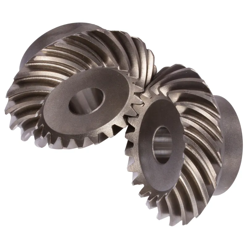
Steel Spiral Bevel Gear Design Features
- Spiral Tooth Geometry
The teeth are curved in a spiral pattern with a helix angle typically around 35 degrees. This design ensures gradual tooth engagement for smoother power transmission. It reduces noise and vibration significantly compared to straight bevel gears. The spiral shape enhances load distribution across multiple teeth. - 1:1 Gear Ratio
Both the pinion and gear have identical tooth counts, resulting in equal rotational speeds. Known as miter gears, they are ideal for applications requiring precise 90-degree power transfer. This ratio maintains consistent torque without speed variation between intersecting shafts. - High-Strength Steel Construction
Made from carbon or alloy steels, these steel spiral bevel gears undergo heat treatment like carburizing or induction hardening. This enhances surface hardness and core toughness. The material choice ensures durability under high loads and resistance to wear in demanding industrial environments. - Precision Tooth Contact
The spiral teeth are machined with high precision to ensure optimal contact patterns. This minimizes backlash and improves efficiency, typically 96-98%. Proper tooth contact reduces frictional losses and heat generation, extending steel bevel gear life in high-speed applications. - Axial Thrust Management
Spiral bevel gears generate axial thrust due to their angled teeth. This requires robust thrust bearings to handle forces effectively. The design accounts for this by incorporating bearing support systems to maintain alignment and prevent premature wear or failure. - Compact Conical Design
The conical shape allows efficient power transfer between intersecting shafts, typically at 90 degrees. This compact design saves space in machinery layouts. It is ideal for applications like automotive differentials, robotics, and aerospace where size constraints are critical.
Steel Spiral Bevel Gear Manufacturing Process
STEP 1: Material Preparation
The manufacturing process begins with selecting high-quality materials, typically steel, to ensure the gear achieves the desired strength, durability, and resistance to wear under demanding conditions.
STEP 2: Cutting
The selected material is cut into smaller, manageable pieces using saws or other cutting tools. This step prepares the raw material for further machining and shaping processes in the production cycle.
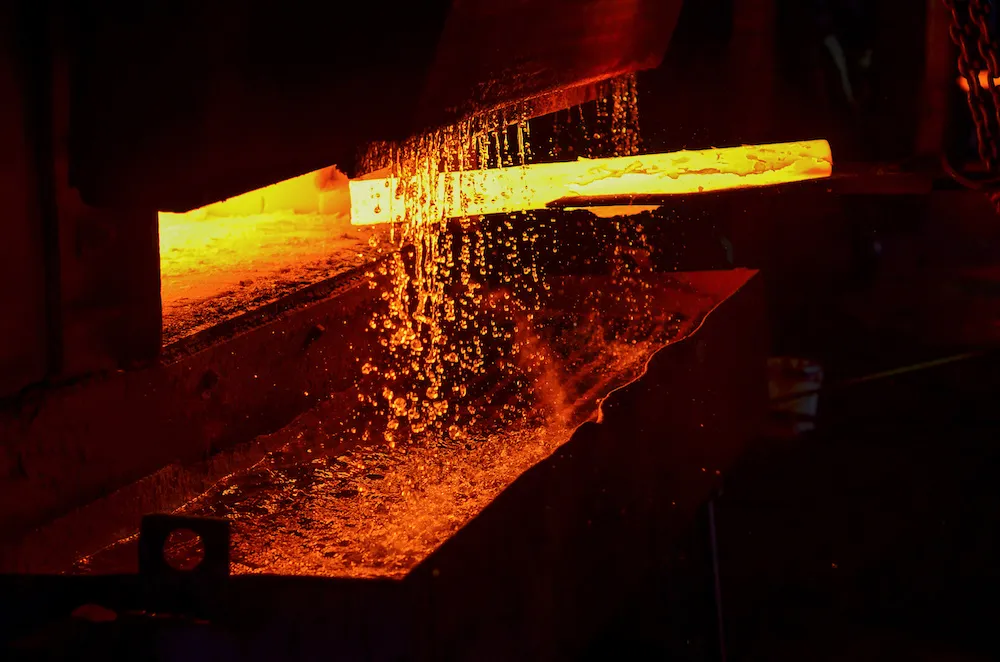
STEP 3: Heat Treatment
The cut material undergoes heat treatment to improve its mechanical properties, such as hardness and toughness. This process ensures the gear can withstand heavy loads and resist deformation.
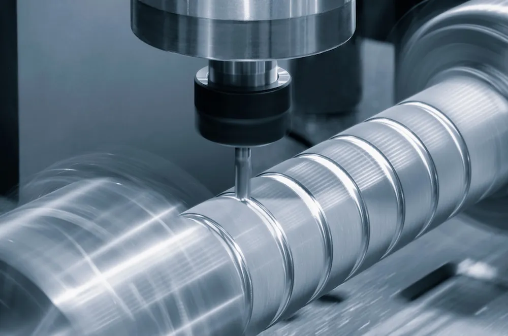
STEP 4: Lathe Machining
The heat-treated material is machined using a lathe to achieve the required cylindrical shape. This step ensures the gear blank is symmetrical and ready for precise tooth cutting.
STEP 5: Gear Cutting
Specialized gear cutting machines are used to form the teeth of the gear. The helical shape of the spiral bevel gear teeth is created with high accuracy during this stage.
STEP 6: Broaching
Internal features such as keyways or splines are produced using a broaching tool. This process removes material to create precise internal structures for proper assembly and functionality.
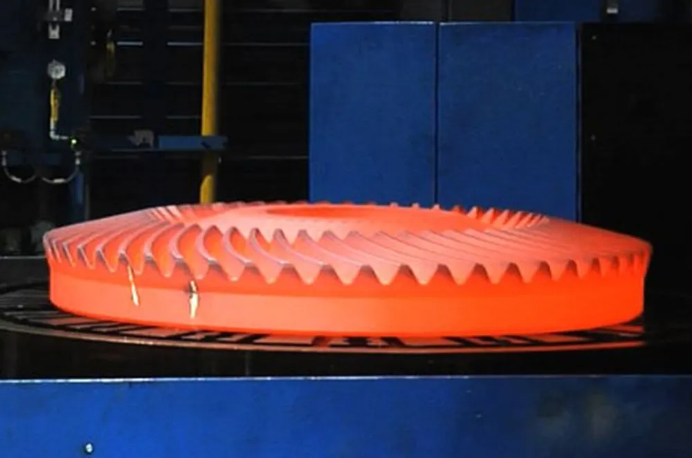
STEP 7: Carburizing with High Frequency
The gear undergoes carburizing, a process that adds carbon to its surface. High-frequency heating is then applied to harden the surface, increasing wear resistance while maintaining a tough core.
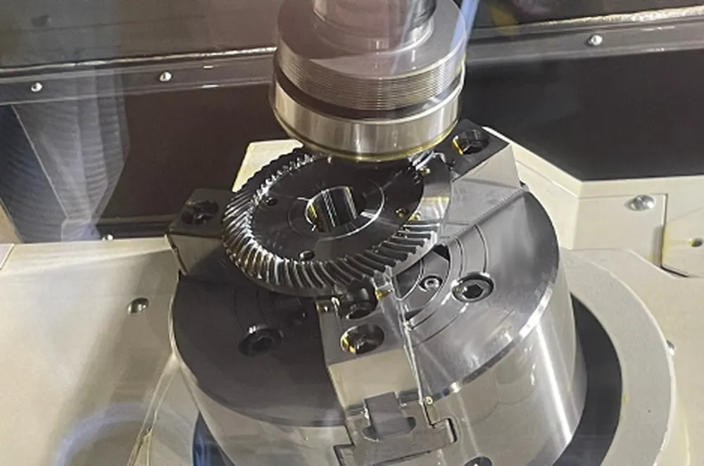
STEP 8: Gear Grinding
Specialized grinding machines are used to finely grind the gear teeth. This step ensures smooth tooth profiles, precise dimensions, and optimal engagement for quiet and efficient operation.
STEP 9: Inspection
The finished gear is meticulously inspected for dimensional accuracy, alignment, and quality. Advanced measuring tools are used to ensure the gear meets design specifications and performs reliably in applications.
 |  |  |
 |  |  |
Applications of Steel Spiral Bevel Gears
- Automotive Differentials
Steel spiral bevel gears are critical in vehicle differentials, transferring power from the driveshaft to the axles at a 90-degree angle. Their smooth engagement and high load capacity ensure reliable performance under varying torque conditions, enhancing vehicle stability and traction. - Industrial Machinery
These spiral gears are used in heavy machinery like milling machines and conveyors, where precise power transmission between intersecting shafts is needed. Their durability and ability to handle high torque make them suitable for continuous operation in harsh industrial environments. - Aerospace Systems
In aircraft and helicopters, steel bevel gears drive critical components like rotor systems. Their compact design and high efficiency ensure reliable power transfer in tight spaces. The gears’ strength withstands extreme conditions, ensuring safety and performance in aerospace applications. - Robotics and Automation
Spiral bevel gears enable precise motion control in robotic arms and automated systems. Their smooth operation and low backlash provide accurate positioning. The 1:1 ratio ensures synchronized movement, critical for tasks requiring high precision in manufacturing and assembly lines. - Marine Propulsion
Used in marine gear systems, these gears transmit power from engines to propellers. Their ability to handle high torque and resist corrosion (when treated) ensures reliable performance in harsh marine environments, supporting efficient vessel operation and maneuverability. - Power Tools
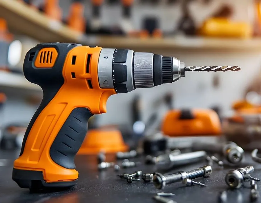
Steel spiral bevel gears are integral in power tools like angle grinders and drills. Their compact design and high efficiency allow for effective power transfer in handheld devices. The gears’ durability ensures consistent performance during prolonged, high-intensity use.
 |  |
| Bevel Gear for Automotive Industry | Bevel Gear for Robotics |
 |  |
| Bevel Gear for Marine Industry | Bevel Gear for Power Tools |
Additional information
| Edited by | Yjx |
|---|